
Method and apparatus for attaching display panels onto wall surface

a technology for display panels and wall surfaces, applied in the direction of electrical apparatus casings/cabinets/drawers, identification means, instruments, etc., can solve the problems of non-pleasant interior decoration of the device, fixtures and cables behind the display device, and the screws holding the device cover or the device itself to the back box, so as to prevent accidental release of the display device

Active Publication Date: 2008-11-18
ELBEX VIDEO LTD
View PDF8 Cites 20 Cited by
  • Summary
  • Abstract
  • Description
  • Claims
  • Application Information

AI Technical Summary

Benefits of technology

[0007]Another objects of the present invention is to provide the holder with springy contacts for connecting all the electrical and signal lines to the flat screen display device or the video interphone unit through a reciprocal contacts affixed onto the rear surface of the flat screen display device or of the video interphone unit, thereby enabling the removal or the attaching of the display device or the video interphone unit without the need to connect or disconnect individual wires or connectors to and from the display device or the video interphone unit itself. The resile force of the springy contacts also provide the force for latching the display device to latching hooks for preventing accidental release of the display device from its holder.
[0008]Another object of the present invention is to provide an embedded back box for installation into walls or other flat surfaces and for attaching a retractable holder onto a spring guided mount plate, through a set of springs extended from the holder into the spring guided mount plate, thereby providing for tightly attaching the display unit, by a spring action onto the wall surface, without the use of visible screws or other fasteners and / or visible fixtures.

Problems solved by technology

The mounts, holders, fixtures and the cables behind the display device are visible and are non-pleasing to the interiors of apartments or offices were they are installed.
The screws holding the device cover or the device itself to the back box are non-pleasing to the interior decoration and are objected by architects and interior designers.
Moreover, to remove for servicing any of the prior art flat screen display devices and / or the video interphone monitors call for disconnection of the wires, cable and plugs and the mechanical disassembly of the device from the mounts, holders, fixtures, the wall and / or the back boxes, which is time consuming and cumbersome.

Method used


Image

  • Method and apparatus for attaching display panels onto wall surface
  • Method and apparatus for attaching display panels onto wall surface
  • Method and apparatus for attaching display panels onto wall surface

Examples


Embodiment Construction

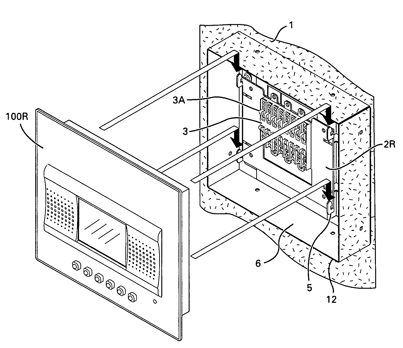
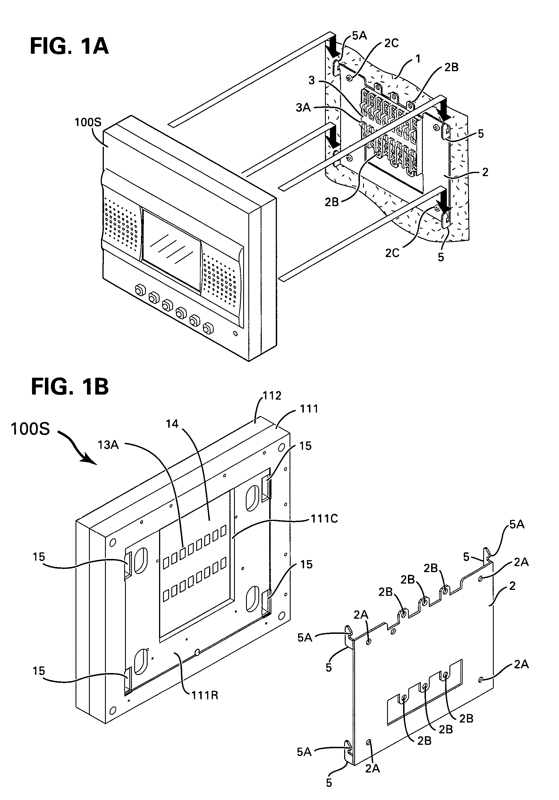
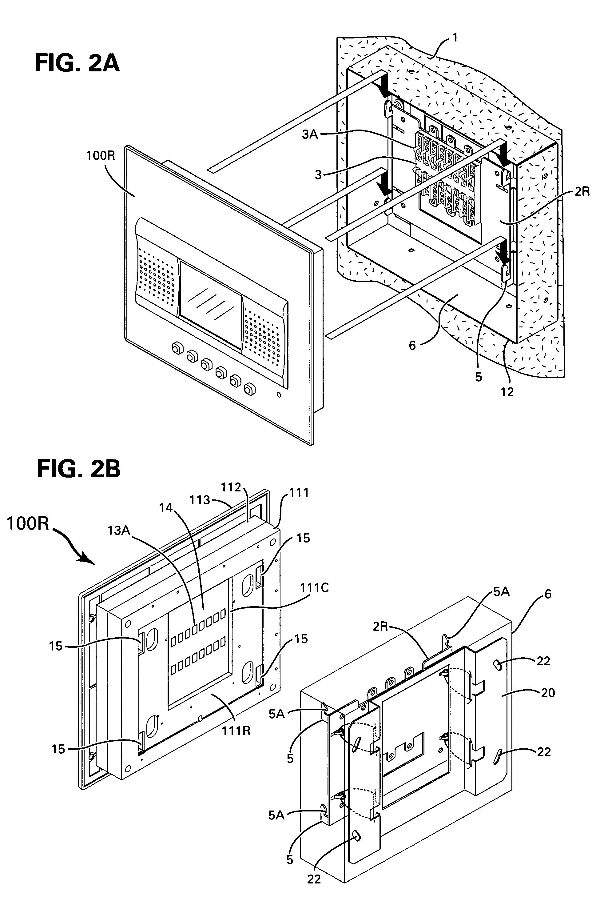
[0020]FIG. 1A shows a flat screen display 100S for surface mounting onto a surface mount 2. A display device in the following description may be flat screen displays such as CRT (cathode ray tube), LCD (liquid crystal display), PDM (plasma display monitor) or LED (light emitting diodes) as used in PC display monitors, or video monitors, or television receivers, or video interphone monitor station, video telephone devices, video conferencing terminals or shopping terminals or other display devices used for displaying data, graphics, pictures and a combination thereof. Surface display device in the following description is a display device 100S shown in FIG. 1A for mounting onto a wall or other flat surfaces such that its entire body protrudes from the surface. Recess display device in the following description is a display device 100R shown in FIG. 2A for mounting onto a wall or other flat surfaces such that the rear portion of the display device is buried into a cutout in the surfac...


PUM


Abstract

A method for attaching a flat screen display device onto a flat surface using a surface mounted holder is disclosed. The holder includes a plurality of springy electrical contacts and a plurality of hooks each having a latch. The rear surface of the display device includes corresponding electrical contacts for corresponding with the plurality of springy electrical contacts and sockets each with a convex area corresponding to the hooks each having a latch. The method includes mounting the sockets onto the hooks and pushing the display device toward the flat surface by overcoming a biasing force of the springy contacts; and sliding the display device in a direction opposite to the direction of the hooks until the springy electrical contacts engage the corresponding electrical contacts and every convex area is latched by every latch, and is secured by the biasing force for preventing accidental release of the display device.

Description

BACKGROUND OF THE INVENTION[0001]1. Field of Invention[0002]This invention relates to the mounting and the connection of flat screen displays such as CRT, LCD, PDP (Plasma Display Monitors) and other flat screen display devices and to the mounting and connection of video interphone monitors used in video interphone systems.[0003]2. Description of the Prior Art[0004]Flat screen display devices such as television receivers, PC displays and monitors are mounted on walls using brackets and holders for attaching the display devices at a distance such as 5 cm˜10 cm (2″˜4″) away from the wall, allowing for a space for the connection of cables and their connectors, such as power, video and audio connectors, to the device. The mounts, holders, fixtures and the cables behind the display device are visible and are non-pleasing to the interiors of apartments or offices were they are installed.[0005]Display devices such as surface mounted video interphone monitors are firmly attached to the wall...

Claims


Application Information

Patent Timeline
Patent Type & Authority Patents(United States)
IPC IPC(8): H05K7/00G09F9/00H04N5/64
CPCF16M13/02H04N5/64Y10S345/905
Inventor ELBERBAUM, DAVID
Owner ELBEX VIDEO LTD
Learn More