System and method for automatically recovering video tools in a vision system

a technology of vision system and video tool, applied in the direction of image analysis, image enhancement, instruments, etc., can solve the problems of aborting further operation of the tool, conventional video tool failure, and failure to operate properly during “run mode” operations, so as to reduce future tool failures

Active Publication Date: 2008-11-18
MITUTOYO CORP
View PDF9 Cites 277 Cited by
  • Summary
  • Abstract
  • Description
  • Claims
  • Application Information

AI Technical Summary

Benefits of technology

[0015]In accordance with another aspect of the invention, in various embodiments the method may include the step of adjusting various operating parameters of a video tool. For example, for various edge detection tools, an edge polarity indicator, one or more edge detection thresholds, or other edge tool parameters may be adjusted based on various characteristics of a current image. Briefly, an edge detection threshold defines the light intensity gradient that a video tool recognizes as indicative of the presence of an edge / boundary feature. Thus, by lowering the edge detection threshold of a video tool, the method renders the tool more sensitive to even “weak” edges having a small light intensity gradient. In many machine vision inspection systems, specific values are determined for one or more edge detection parameters associated with a specific workpiece feature, by “training” an edge detection tool positioned to inspect the feature, during a learn mode of operations. Such training is routinely performed automatically during learn mode operations and the associated parameter values are stored in association with a part program for inspecting the associated workpiece.
[0021]In accordance with a further aspect of the invention, in some embodiments the automatic tool recovery instructions are configured to keep track of the types of video tools that have failed and / or the types of adjustments that have been performed to recover each tool, in relation to a particular feature, and / or workpiece, and / or machine vision inspection system. Such data can be compiled and analyzed by the user, for example, to investigate the frequent causes of a tool failure in order to reduce future tool failures. For example, based on the analysis, the user might adjust or repair a machine, and / or optimally define various hardware / software parameters for the proper operation of each tool, and / or optimally configure various related recovery operations, either globally, or in relation to a particular tool.

Problems solved by technology

However, during subsequent repeated automatic operation of the video tool in run mode, various unforeseen variations in part fabrication, part fixturing, vision machine degeneration, ambient lighting condition, and the like, may contribute to a set of operating conditions that are not suitable for the proper operation of the video tool according to its previously established operating parameters.
Thus, conventional video tools may fail to operate properly during “run mode” operations, for example, due to one or more unexpected variations in operating conditions or workpiece characteristics.
Conventional video tools may also fail to operate properly during “learn mode” operations, because a relatively inexperienced user may be unable to set the relevant machine, image, or video tool parameters correctly, due to poor understanding of the operation of the tool and / or inexperience regarding its application.
Currently, when a conventional video tool fails to operate properly, further operation of the tool is aborted and a user is forced to intervene and recover the tool manually, e.g., by manually adjusting the camera position relative to the workpiece, and / or adjusting the lighting, and / or adjusting various parameters of the video tool.
This is a cumbersome and time-consuming procedure, which significantly reduces operator productivity during learn mode and / or the inspection throughput of the vision system during run mode.

Method used


Image

  • System and method for automatically recovering video tools in a vision system
  • System and method for automatically recovering video tools in a vision system
  • System and method for automatically recovering video tools in a vision system

Examples


Embodiment Construction

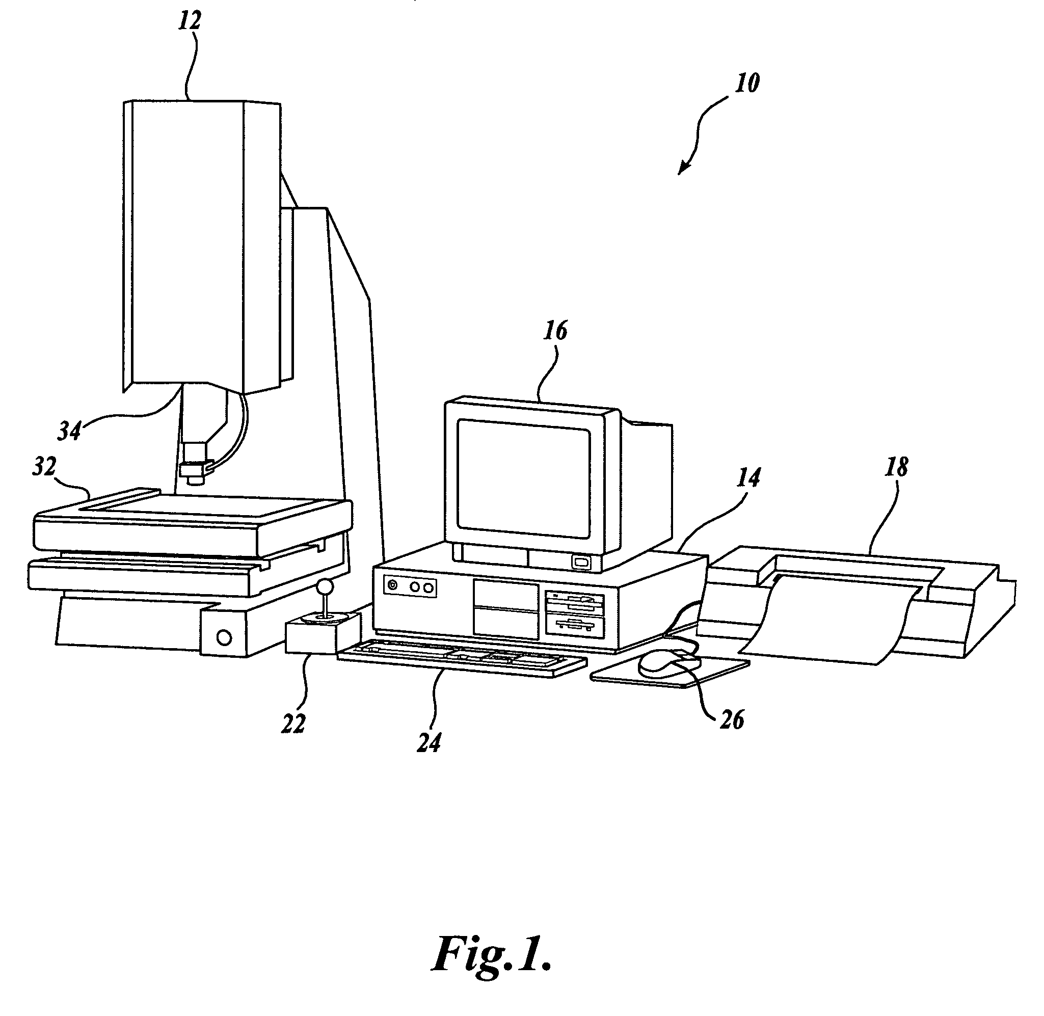
[0032]FIG. 1 is a block diagram of one exemplary machine vision inspection system 10 in accordance with the present invention. The machine vision inspection system 10 includes a vision measuring machine 12 that is operably connected to exchange data and control signals with a controlling computer system 14. The controlling computer system 14 is further operably connected to exchange data and control signals with a monitor 16, a printer 18, a joystick 22, a keyboard 24, and a mouse 26. The vision measuring machine 12 includes a moveable workpiece stage 32 and an optical imaging system 34 which may include a zoom lens or interchangeable lenses. The zoom lens or interchangeable lenses generally provide various magnifications for the images provided by the optical imaging system 34.

[0033]The joystick 22 can typically be used to control the movement of the movable workpiece stage 32 in both X and Y directions, which are generally parallel to the focal plane of the optical imaging system ...


PUM


Abstract

Methods and systems for automatically recovering a failed video inspection tool in a precision machine vision inspection system are described. A set of recovery instructions may be associated or merged with a video tool to allow the tool to automatically recover and proceed to provide an inspection result after an initial failure. The recovery instructions include operations that evaluate and modify feature inspection parameters that govern acquiring an image of a workpiece feature and inspecting the feature. The set of instructions may include an initial phase of recovery that adjusts image acquisition parameters. If adjusting image acquisition parameters does not result in proper tool operation, additional feature inspection parameters, such as the tool position, may be adjusted. The order in which the multiple feature inspection parameters and their related characteristics are considered may be predefined so as to most efficiently complete the automatic tool recovery process.

Description

FIELD OF THE INVENTION[0001]The invention relates generally to methods for operating a machine vision inspection system with a camera and stage that are movable relative to one another in multiple directions so as to scan and inspect selected features of a workpiece on the stage, and more particularly to systems and methods that automatically recover or augment the operation of video-based inspection / measuring tools used in such a vision system.BACKGROUND OF THE INVENTION[0002]Precision machine vision inspection systems (or “vision systems” in short) can be utilized to obtain precise dimensional measurements of inspected objects and to inspect various other object characteristics. Such systems may include a computer, a camera and optical system, and a precision stage that is movable in multiple directions so as to allow the camera to scan the features of a workpiece that is being inspected. One exemplary prior art system that is commercially available is the QUICK VISION® series of ...

Claims


Application Information

Patent Timeline
Patent Type & Authority Patents(United States)
IPC IPC(8): G06K9/00G06V10/26
CPCG06T7/0004G06T2207/30164G06V10/26G06V10/457G06V2201/06G06V10/945
Inventor BRYLL, ROBERT K.ARIGA, KOZO
Owner MITUTOYO CORP
Why Eureka
Try Eureka