
Image editing method, image editing apparatus, program for implementing image editing method, and recording medium recording program

a technology of image editing and image processing apparatus, applied in the field of image editing technique, can solve the problems of difficult for users to take photographs with desired composition, and difficult for users to grasp impressions, etc., to achieve the effect of reducing the number of operations, facilitating movement and magnification of images, and determining the composition of images with eas

Inactive Publication Date: 2008-11-18
CANON KK
View PDF63 Cites 6 Cited by
  • Summary
  • Abstract
  • Description
  • Claims
  • Application Information

AI Technical Summary

Benefits of technology

[0014]An object of the present invention is to provide an image editing technique that enables a user to perform movement and magnification of an image with ease by the less number of operations performed by the user.
[0015]Further, another object of the present invention is to provide an image editing technique with which at the time of trimming an image photographed with a digital camera or the like, it is possible to determine composition of the image with ease.

Problems solved by technology

However, there is a shortcoming that it is difficult for the user to grasp an impression that would be given by post-trimming image composition when the image is actually printed in a print area.
Also, such the determination of composition itself is burdensome for some users, so that even if it is possible to obtain photographs beyond recognition through trimming of images, they often print the images without using the trimming function.
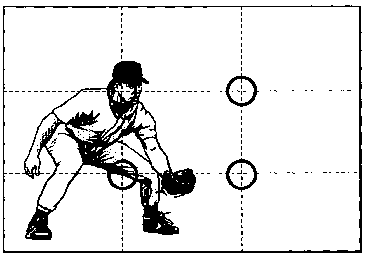
In a like manner, when a moving subject is photographed like in an example shown in FIG. 15A, it is difficult to take a photograph having desired composition.
Even in this case, however, it is difficult for a user, in particular for a beginner, to determine a position where the go-cart (main object in this case) should be positioned through trimming in order to obtain a generally favorable composition.

Method used


Image

  • Image editing method, image editing apparatus, program for implementing image editing method, and recording medium recording program
  • Image editing method, image editing apparatus, program for implementing image editing method, and recording medium recording program
  • Image editing method, image editing apparatus, program for implementing image editing method, and recording medium recording program

Examples


first embodiment

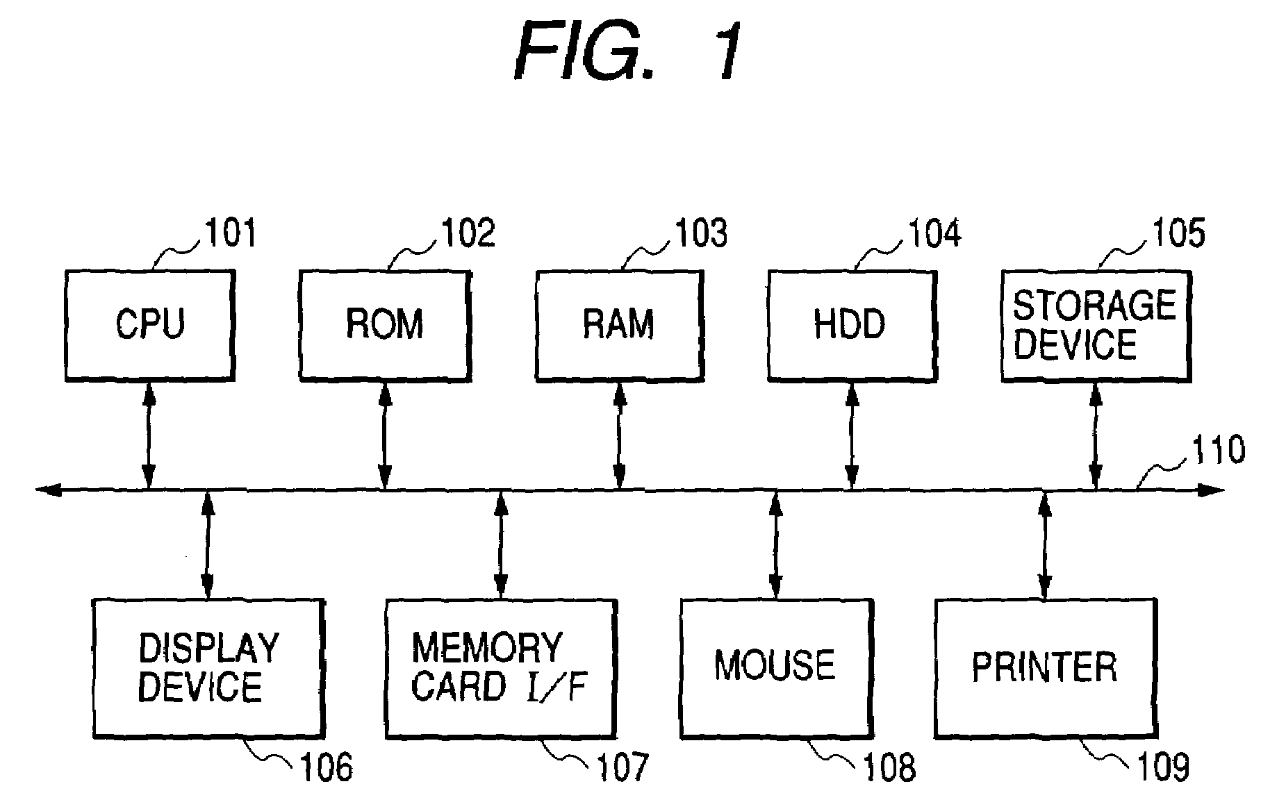
[0041]FIG. 1 shows an example of a hardware construction of an image editing apparatus according to first to sixth embodiments of the present invention. In this drawing, reference numeral 101 denotes a CPU (central processing unit) that executes computer software programs; numeral 102, a ROM (read-only memory) in which programs are stored; numeral 103, a RAM (random-access memory) that is used at the time of execution of the programs; numeral 104, a hard disk drive (HDD) in which the programs are stored; numeral 105, a storage device that stores programs and data on a medium such as a flexible disk or an MO (magneto-optical disk); numeral 106, a display device for displaying execution results and execution states of the programs; numeral 107, a memory card interface into which a memory card is inserted and which writes and reads data into and from the inserted memory card; numeral 108, a mouse and a keyboard; numeral 109, a printer; and numeral 110, a bus.

[0042]In this embodiment, t...

second embodiment

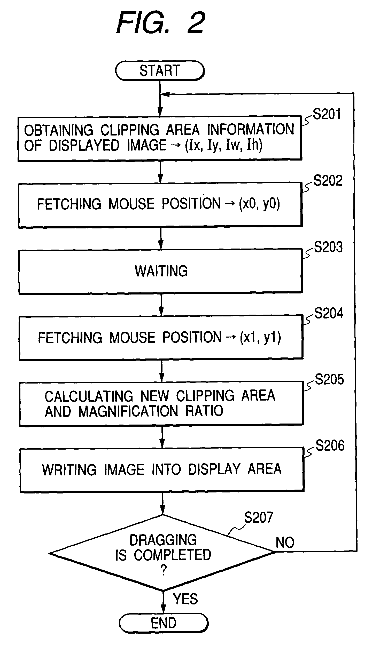
[0064]FIG. 7 is a flowchart showing a process performed with an image editing method according to a second embodiment of the present invention. Hereinafter, the second embodiment of the present invention will be described by following this flowchart. When a dragging operation with the mouse is performed, the following process is started.

[0065]In step S701, the position (Ix, Iy), width Iw, and height Ih of the clipping frame (trimming frame) on the image coordinate system at that point in time are obtained. In the same manner as in the first embodiment, the position of the upper left-hand point of the clipping frame on the image coordinate system is substituted into (Ix, Iy) and the width and height of the clipping frame thereon are substituted into (Iw, Ih).

[0066]In step S702, the coordinate of the pre-movement position of the mouse on the display memory coordinate system is fetched and is substituted into (x0, y0).

[0067]In step S703, a waiting operation is performed for a given len...

third embodiment

[0077]FIG. 3 is a flowchart showing a process performed with an image editing method according to a third embodiment of the present invention. Hereinafter, the third embodiment of the present invention will be described by following this flowchart. When a dragging operation with the mouse is performed, the following process is started.

[0078]In step S301, the position, width, and height of the clipping frame (trimming frame) on the image coordinate system under an initial state are obtained. The position of the upper left-hand point of the clipping frame on the image coordinate system is set as (Isx, Isy) and the width and height of the clipping frame thereon are set as (Isw, Ish).

[0079]In step S302, the coordinate (sx0, sy0) of the pre-movement position of the mouse on the display memory coordinate system is fetched.

[0080]In step S303, the position, width, and height of the clipping frame on the image coordinate system at that point in time are obtained. That is, the position of the...


PUM


Abstract

To provide an image editing technique that enables a user to perform movement and magnification of an image with a single operation, and to perform trimming while grasping image composition in printing, the image editing method includes a step of instructing to move an arbitrary point of an image displayed in an image display area among image data; a step of calculating an image movement amount and a magnification ratio in response to the instruction to move the arbitrary point; and a step displaying a predetermined area of the image data in the image display area on the basis of the image movement amount and the magnification ratio, which are calculated in the calculating step.

Description

BACKGROUND OF THE INVENTION[0001]1. Field of the Invention[0002]The present invention relates to an image editing technique, and in particular to a technique with which when a still image or a moving image photographed with a digital still camera, a digital video camera, or the like is to be displayed and / or printed, composition of the image may be adjusted while displaying the image.[0003]2. Related Background Art[0004]Commonly used is a function with which image data photographed with a digital camera is fetched and is displayed on a display device, an arbitrary area of the image is designated as a trimming area using a pointing device such as a mouse or a remote controller, and the designated trimming area is printed. FIG. 6 shows an example of a very commonly performed trimming process. In this drawing, a trimming frame 602 is displayed so that it is superimposed on a pre-trimming image 601, and a user designates his / her desired part of the image 601 by reducing / magnifying, rota...

Claims


Application Information

Patent Timeline
Patent Type & Authority Patents(United States)
IPC IPC(8): G06F3/00G06F3/048G06T3/40G06T11/60
CPCG06T11/60G06F3/0484
Inventor MATSUMOTO, KENTARO
Owner CANON KK
Learn More