Elevator roller guide

a technology of roller guides and elevators, which is applied in the direction of elevators, rope railways, transportation and packaging, etc., can solve the problems of difficulty in having one roller guide device design readily integrated into a variety of elevator systems, and achieve the effect of convenient centering of the elevator cab

Inactive Publication Date: 2008-11-25
OTIS ELEVATOR CO
View PDF11 Cites 5 Cited by
  • Summary
  • Abstract
  • Description
  • Claims
  • Application Information

AI Technical Summary

Benefits of technology

[0009]In general terms, this invention is a roller guide device that maintains appropriate contact between rollers and a guide rail and centers the roller guide, which facilitates centering the elevator cab.
[0010]One example roller device designed according to this invention includes a base. A roller mount is moveably secured to the base. Rollers are supported on the mount with their axes a fixed distance from each other. A biasing member urges the mount into a position where the rollers engage a guide rail without changing the distance between the rollers to establish appropriate roller and guide rail contact and to center the roller guide, which facilitates centering the elevator cab.

Problems solved by technology

One challenge facing designers of such devices is to provide for appropriate tolerances in the spacing of the rollers so that smooth movement of the cab is achieved by appropriate cooperation between the rollers and the guide rail nose surfaces.
Manufacturing tolerances and variations in the surfaces on the guide rails make it difficult to have one roller guide device design be readily incorporated into a variety of elevator systems.

Method used


Image

  • Elevator roller guide
  • Elevator roller guide
  • Elevator roller guide

Examples


Embodiment Construction

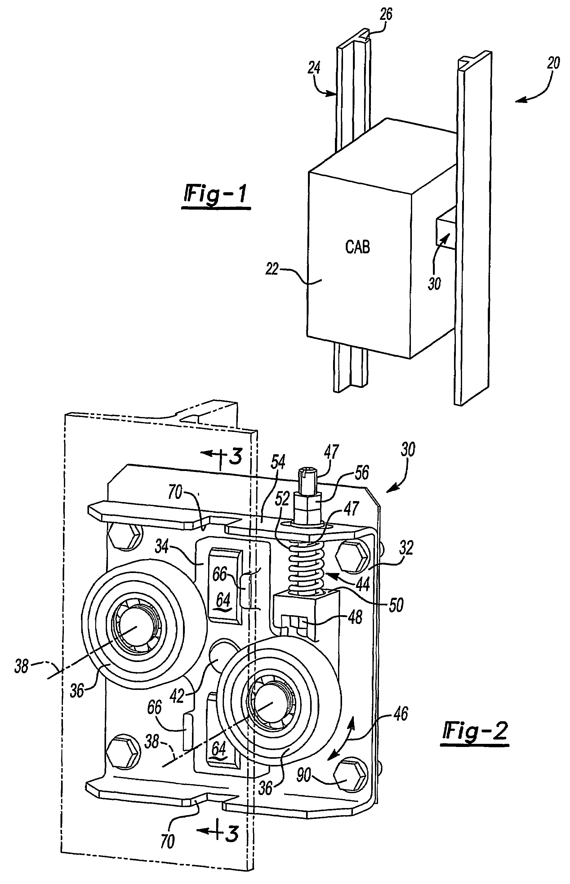
[0021]FIG. 1 schematically illustrates an elevator system 20. An elevator cab 22 moves along guide rails 24 in a known manner. The guide rails 24 are secured within a hoistway, for example, in a conventional manner so that a nose portion 26 of the T-shaped guide rails 24 faces toward the elevator cab 22.

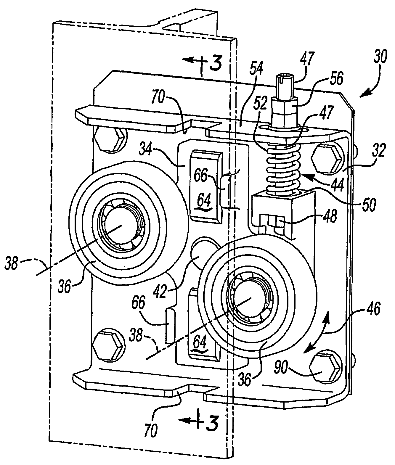
[0022]At least one self-centering roller guide device 30 is supported on the cab to cooperate with each of the guide rails 24. More particularly, the roller guide device 30 includes rollers that roll along the oppositely facing surfaces of the nose portion 26 of the guide rails 24.

[0023]FIG. 2 illustrates one example roller guide device designed according to this invention. The guide device 30 includes a rigid base 32, which may be made from steel, for example. The base 32 is adapted to be mounted in a fixed position relative to the cab 22.

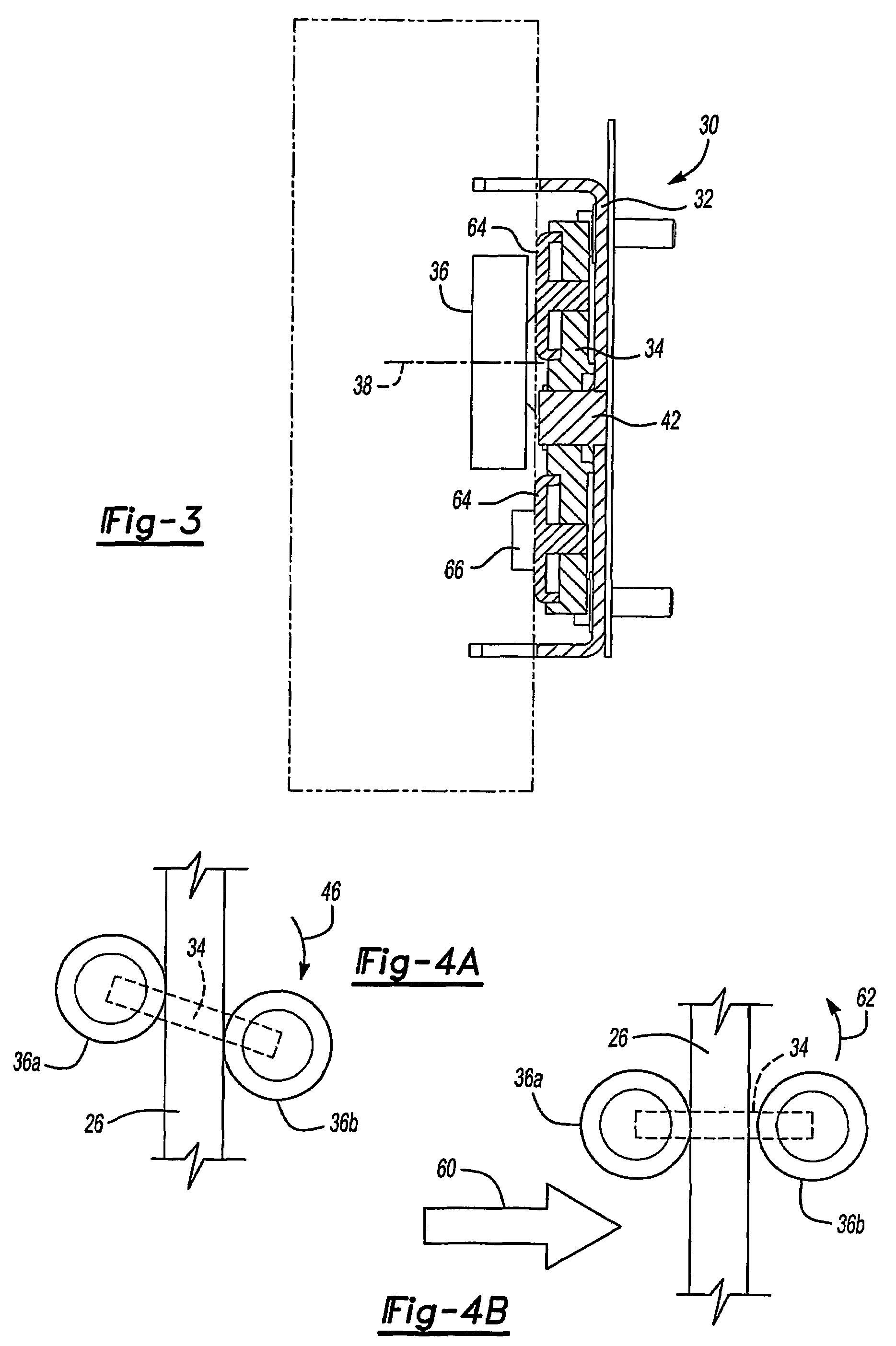
[0024]A roller mount 34 is moveably supported by the base 32 such that the roller mount 34 can move relative to the base 32. A set of rollers 36 a...


PUM


Abstract

A guiding device (30) for an elevator system (20) facilitates guiding a cab (22) along guide rails (24). The guiding device (30) includes a roller mount (34) that supports rollers (36) such that the rollers remain a fixed distance from each other. A biasing member (44) urges the mount (34) in a direction that maintains contact between the guide rail (24) and the rollers (36) and facilitates centering the guiding device (30) and the cab (22) relative to the guide rails (24).

Description

BACKGROUND OF THE INVENTION[0001]1. Field of the Invention[0002]This invention generally relates to elevator systems. More particularly, this invention relates to a roller guide device for use in an elevator system.[0003]2. Description of the Prior Art[0004]Elevator systems are well known. A cab typically is guided within a hoistway along guide rails that extend vertically within the hoistway. Various configurations of guiding arrangements have been developed to provide smooth movement of the cab along the guide rails.[0005]Typical guiding arrangements include rollers that roll along corresponding surfaces on a nose of the guide rail. One challenge facing designers of such devices is to provide for appropriate tolerances in the spacing of the rollers so that smooth movement of the cab is achieved by appropriate cooperation between the rollers and the guide rail nose surfaces. Manufacturing tolerances and variations in the surfaces on the guide rails make it difficult to have one rol...

Claims


Application Information

Patent Timeline
Patent Type & Authority Patents(United States)
IPC IPC(8): B66B7/04B66B7/02
CPCB66B7/046B66B7/048B66B7/02B66B7/04
Inventor PEREZ, JOSE SEVILLEJA
Owner OTIS ELEVATOR CO
Why Eureka
Try Eureka