Moving magnet actuation of tape head

a technology of moving magnets and tape heads, which is applied in the direction of magnetic recording, instruments, data recording, etc., can solve the problems of limiting the number of data tracks, significant waste of magnetic tape surfaces, and limiting the data density of tapes, so as to facilitate dynamic response and reduce the force of constraint in pivoting. , the effect of pure torqu

Active Publication Date: 2009-08-13
TWITTER INC
View PDF38 Cites 4 Cited by
  • Summary
  • Abstract
  • Description
  • Claims
  • Application Information

AI Technical Summary

Benefits of technology

[0012]The lateral position of tracks on a moving tape are sensed and in response, the lever and hence the tape read/write head carried by the lever, may be pivoted relative to a first support frame. In the illustrated embodiment, the lever and hence the tape read/write head carried by the lever, may be pivoted by conducting current through a coil to generate a magnetic field which is conducted by the return path structure to interact with the magnetic field of the magnet. As a result, the lever pivots on a pivot axis as a function of the magnitude and direction of the curren

Problems solved by technology

However, the definition of the magnetic read/write head and the track widths and separations can limit the number of data tracks that may be recorded on any given width of tape.
Reliance solely on the track width and track separations for reliable read/write operations can result in a significant waste of magnetic tape surface and thus limit the data density on the tape.
However, as the track width and the read/write head width narrow in an effort to increase the data capacity of a given tape area, any misalignment of the head with the track may lead to read/write repeatability failures and lost data.
Thus, the resolution of the head placement mechanism and the pre

Method used


Image

  • Moving magnet actuation of tape head
  • Moving magnet actuation of tape head
  • Moving magnet actuation of tape head

Examples


Embodiment Construction

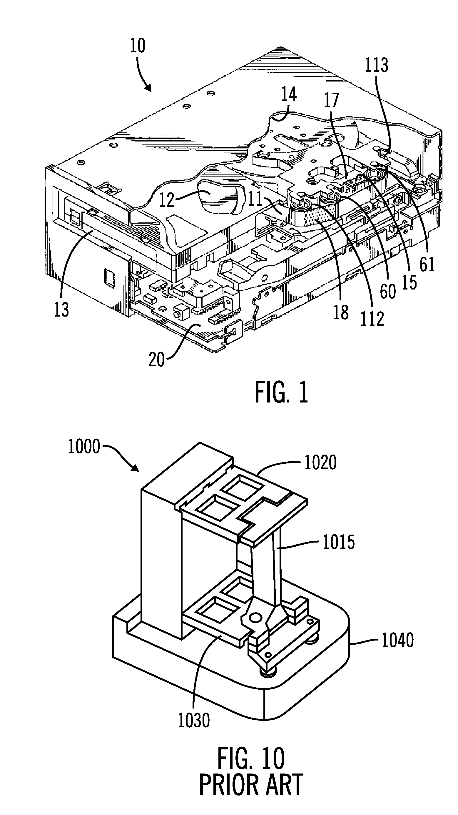
[0025]In the following description of the exemplary embodiment, reference is made to the accompanying drawings which form a part hereof, and in which is shown by way of illustration a specific embodiment which may be practiced. It is to be understood that other embodiments may be utilized as structural changes may be made without departing from the scope of the present description.

[0026]In one embodiment, a balanced actuator is provided for a tape head. It is believed that an actuator in accordance with the present description can perform well in a shock and vibration environment. In addition, a spring or other flexture may be eliminated. It is appreciated that other features may be realized, depending upon the particular application.

[0027]In one aspect, the mass of the tape head may be balanced by the mass of a movable permanent magnet. When a coil of the actuator is not energized, the magnet may be arranged to be self centering in the middle of a gap between fixed pole pieces. As ...


PUM


Abstract

In one embodiment, a tape read/write head supported by a lever is biased in a first position, using magnetic attraction between a magnet supported by the lever, and a return path structure of magnetically permeable material. In the illustrated embodiment, the magnet centers itself, in the absence of a coil generated magnetic field, in the middle of a gap of the magnetic return path structure. In one aspect, the mass of the read/write head and one side of the lever may be balanced by the mass of the magnet and the other side of the lever. The lever and hence the tape read/write head carried by the lever, may be pivoted by conducting current through a coil to generate a magnetic field which is conducted by the return path structure to interact with the magnetic field of the magnet. As a consequence, the lever pivots on a pivot axis as a function of the magnitude and direction of the current through the coil. The face of the magnet may be divided into portions of opposite magnetic polarity to facilitate a relatively pure torque to be developed substantially without a net force. Other embodiments are described and claimed.

Description

BACKGROUND[0001]Data storage on magnetic tape is well known and tape recorders have been used to record data tracks on magnetic tape. Traditionally, data is recorded in a plurality of parallel data tracks on the magnetic tape. The read / write head is then positioned relative to the tape path by moving the head to different track positions as desired. In such a system, the tape tracks are generally sufficiently wide and separated to facilitate reliably reading and writing the data.[0002]In one approach, the read / write head may be positioned at a predetermined fixed point, relative to the magnetic tape path, and the data tracks are intended to accommodate variations of recording track location and tape locations as the tape feeds past the head. Historically, this accommodation has been accomplished by providing sufficient track width and data track separation on the magnetic tape to permit the read / write head to remain positioned over the designated track and at the same time not read ...

Claims


Application Information

Patent Timeline
IPC IPC(8): G11B5/584
CPCG11B5/584
Inventor BUI, NHAN XUANHANCOCK, REED ALANHARPER, DAVID HOWARD FLORESIMAINO, WAYNE ISAMI
Owner TWITTER INC
Why Eureka
Try Eureka