Caliper casting device, core and mold used in caliper casting device, caliper for disc brake, and manufacturing method thereof

a casting device and disc brake technology, applied in the direction of manufacturing tools, foundry patterns, molds, etc., can solve the problems of affecting the quality of casting products, and it is difficult to sufficiently prevent the shrinkage cavity, so as to increase the assembling position of the cor

Active Publication Date: 2018-01-23
AKEBONO BRAKE IND CO LTD
View PDF17 Cites 3 Cited by
  • Summary
  • Abstract
  • Description
  • Claims
  • Application Information

AI Technical Summary

Benefits of technology

[0009]The present invention is achieved in view of the above described problem, and has an object to provide a technique capable of favorably preventing generation of a shrinkage cavity in solidification of molten metal poured into a casting mold, and increasing accuracy of an assembling position of a core to a mold, in casting a caliper.
[0011]According to the present invention, the rotor housing surface of the caliper may be formed by the core, and also the rotor housing surface forming portion that is formed as a part of the mold having higher thermal conductivity than the core. Specifically, casting the caliper with the core being positioned and held by the rotor housing surface forming portion of the mold can increase a cooling speed of molten metal in an area for forming the cylinder or the rotor housing surface of the caliper, and accelerate timing for solidification, as compared to a conventional example. This can prevent generation of a shrinkage cavity in the cylinder or the rotor housing surface of the caliper obtained by casting. Also, according to the present invention, during casting, the core is positioned and held in the rotor housing surface forming portion of the mold, thereby increasing accuracy of an assembling position of the core to the mold. Specifically, according to the present invention, the caliper casting device can be provided that can favorably prevent generation of a shrinkage cavity in solidification of molten metal poured into the casting mold, and increase accuracy of an assembling position of the core to the mold, in casting the caliper.
[0012]In the caliper casting device according to the present invention, a positioning groove that positions and holds the core may be formed in the rotor housing surface forming portion, the core may include a cylinder forming portion that forms the cylinder after casting, and a core print portion coupled to the cylinder forming portion, and the core print portion may have a fitted portion that can be fitted in the positioning groove and forms the rotor housing surface together with the rotor housing surface forming portion after casting. As such, the positioning groove for positioning and holding the core is provided in the rotor housing surface forming portion that is formed as a part of the mold, and the fitted portion included in the core print portion of the core is fitted in the positioning groove, thereby further increasing assembling accuracy of the core. In the caliper casting device according to the present invention, in pouring the molten metal into the mold, the fitted portion of the core may be fitted in the positioning groove provided in the rotor housing surface forming portion. Thus, for example, in a state where the mold is preheated and expanded in a process before the molten metal is poured into the mold (previous process), the fitted portion of the core may be fitted in the positioning groove in the mold. In the present invention, the rotor housing surface forming portion preferably has higher thermal conductivity than the core. Thus, a cooling speed of the molten metal in the area for forming the cylinder or the rotor housing surface of the caliper after casting can be more favorably adjusted.
[0013]The positioning groove may include a first groove, and a second groove intersecting the first groove, and the fitted portion may be fitted in the first groove and the second groove. The fitted portion formed in the core print portion of the core is thus fitted in the first groove and the second groove intersecting each other, and thus the positioning groove including the first groove and the second groove functions as a guide for placing the core. This can facilitate centering in assembling of the core, and further increase accuracy of an assembling position. The first groove and the second groove may be linear grooves and perpendicular to each other. This allows the core to be bilaterally symmetrical and increases machinability of the mold. Specifically, machining accuracy of the mold can be increased, and thus accuracy of the assembling position of the core to the mold can be also increased, thereby increasing dimension accuracy of a casting product. The shape formed by the first linear groove and the second linear groove perpendicular to each other may include both a cross shape and a T shape. Specifically, the positioning groove may include at least the first linear groove and the second linear groove, and the positioning groove may be formed with other grooves being added. Thus, the positioning groove may have a cross shape, a T shape, and also an H shape, a # shape, or the like. The positioning groove may have a shape other than these exemplified shapes.
[0014]The core print portion may further include a stopper portion that is provided at an end of the fitted portion and is wider than the positioning groove, and the stopper portion may have a stepped surface that abuts against a side surface intersecting the positioning groove in the rotor housing surface forming portion when the fitted portion is fitted in the positioning groove. With such a configuration, the positioning accuracy of the core in placing the core in the mold can be further increased. Also, displacement of the core from a normal position due to a flow of the poured molten metal when the molten metal is poured into the mold can be favorably prevented. The side surface of the mold against which the stepped surface of the stopper portion abuts when the core is assembled to the mold may be perpendicular to the positioning groove in the rotor housing surface forming portion.
[0022]According to the present invention, a technique can be provided capable of favorably preventing generation of a shrinkage cavity in solidification of molten metal poured into a casting mold, and increasing accuracy of an assembling position of a core to a mold, in casting a caliper.

Problems solved by technology

Thus, a shrinkage cavity due to shrinkage in a solidification process of the molten metal may be formed in the caliper obtained as a cast, which may affect quality of a casting product.
However, as illustrated in FIG. 12, in the conventional core 200, the base 210 has a relatively large volume, and it is actually difficult to sufficiently prevent the shrinkage cavity.

Method used


Image

  • Caliper casting device, core and mold used in caliper casting device, caliper for disc brake, and manufacturing method thereof
  • Caliper casting device, core and mold used in caliper casting device, caliper for disc brake, and manufacturing method thereof
  • Caliper casting device, core and mold used in caliper casting device, caliper for disc brake, and manufacturing method thereof

Examples


embodiment 1

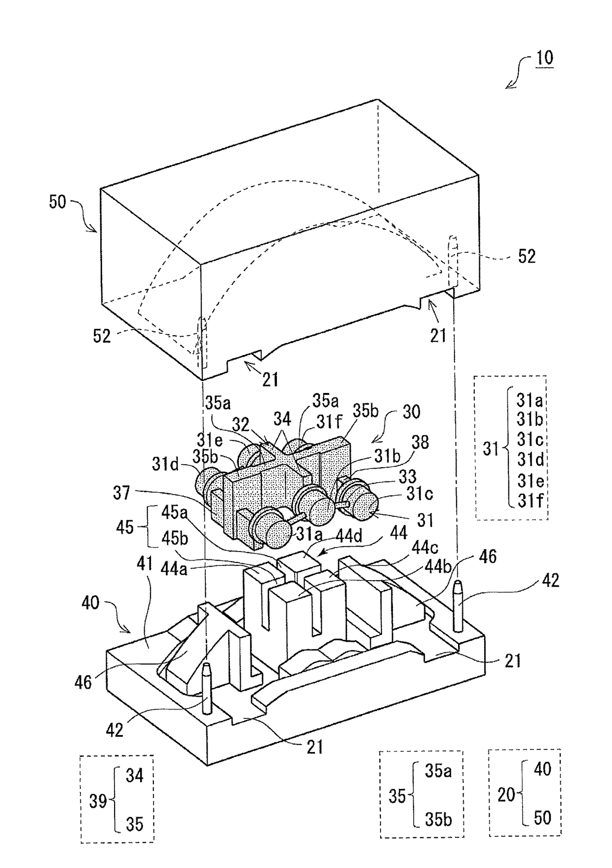
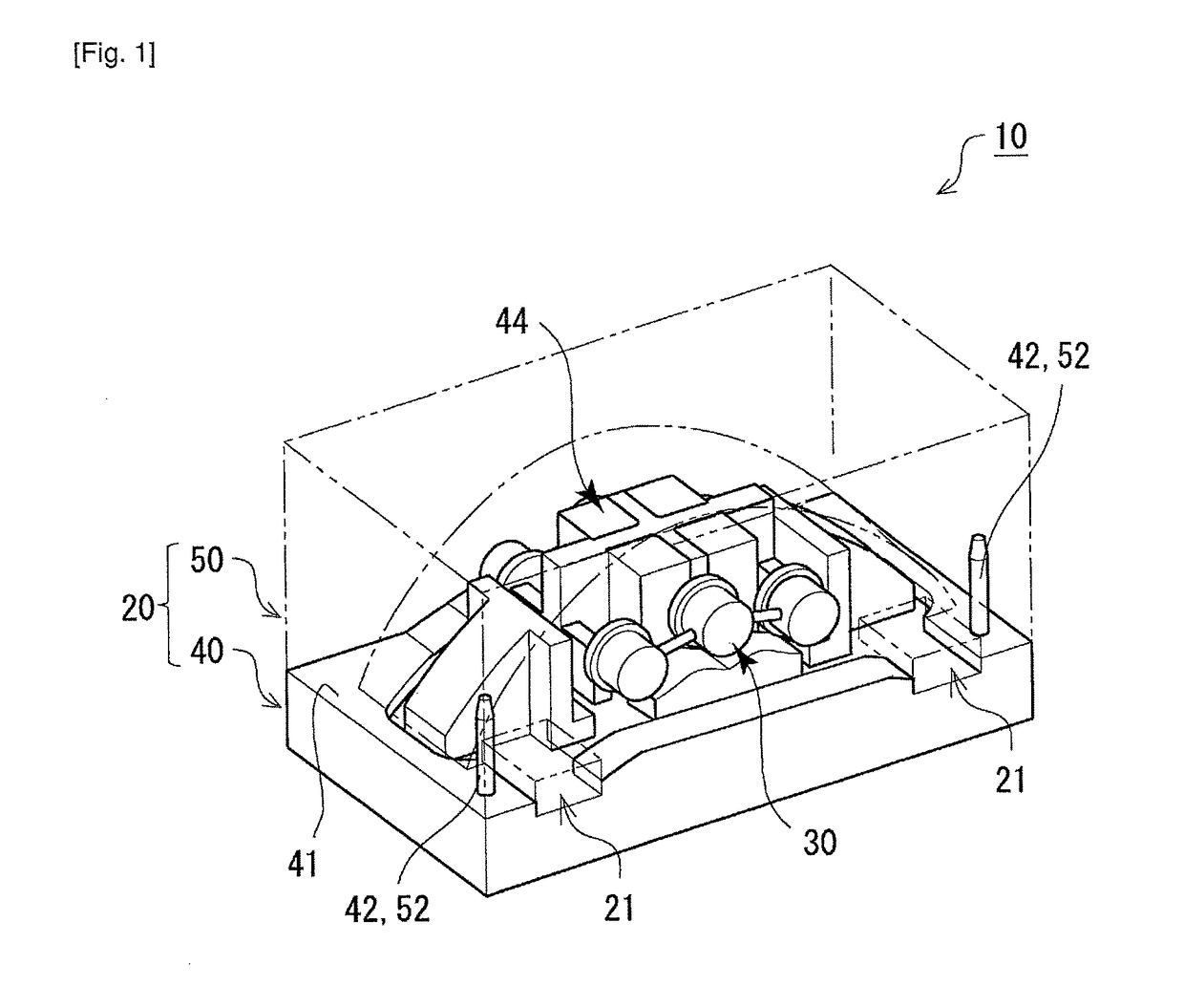
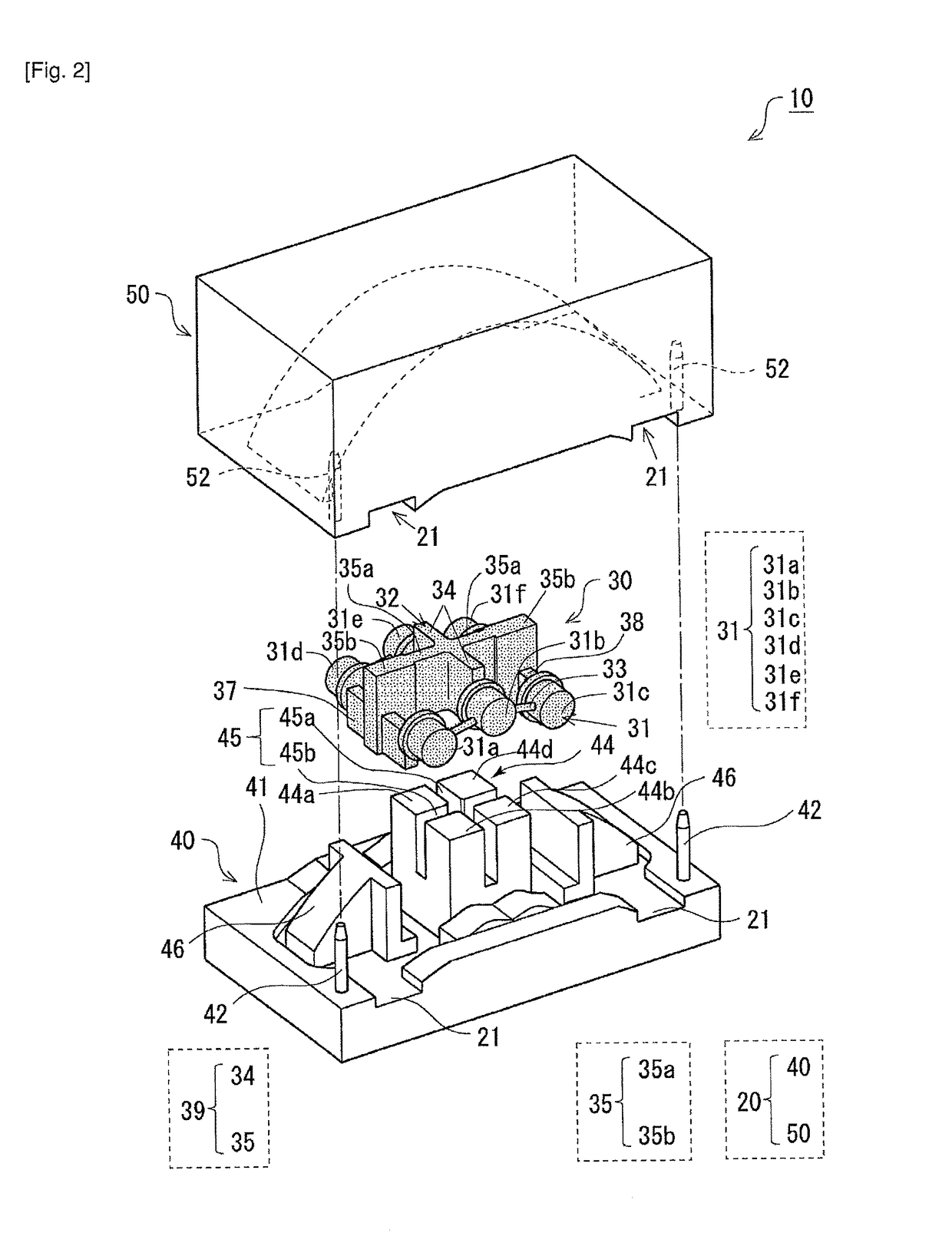
[0038]FIG. 1 illustrates a schematic configuration of a caliper casting device according to Embodiment 1. FIG. 2 is an exploded perspective view of the caliper casting device according to Embodiment 1. FIG. 3 illustrates a lower mold (die) in which a core that constitutes the caliper casting device according to Embodiment 1 is placed. FIG. 4 illustrates an upper mold (die) that constitutes the caliper casting device according to Embodiment 1. FIGS. 5 to 9 illustrate an example of an appearance of a caliper 1 casted by the caliper casting device according to Embodiment 1. FIG. 5 is an orthographic view of the caliper 1 according to Embodiment 1 seen from an outer diameter side of a disc rotor. FIG. 6 is an orthographic view of the caliper 1 according to Embodiment 1 seen from one lateral side. FIG. 7 is an orthographic view of the caliper 1 according to Embodiment 1 seen from the other lateral side. FIG. 8 is a main sectional view of the caliper 1 according to Embodiment 1. FIG. 9 is...


PUM

PropertyMeasurementUnit
solidification shrinkageaaaaaaaaaa
thermal conductivityaaaaaaaaaa
braking forceaaaaaaaaaa

Abstract

A technique is provided capable of favorably preventing generation of a shrinkage cavity in solidification of molten metal poured into a casting mold, and increasing accuracy of an assembling position of a core to a mold, in casting a caliper. A caliper casting device for casting a caliper for a disc brake including a cylinder into which a piston is fitted, and a rotor housing surface that defines a space for housing a disc rotor, includes: a mold; and a core placed in the mold, the mold having a rotor housing surface forming portion that forms a part of the rotor housing surface after casting, and the core being positioned and held in the rotor housing surface forming portion during casting, and forming a part of the rotor housing surface together with the rotor housing surface forming portion after casting.

Description

TECHNICAL FIELD[0001]The present invention relates to a caliper casting device, a core and a mold used in a caliper casting device, a caliper for a disc brake, and a manufacturing method thereof.BACKGROUND ART[0002]A disc brake is widely used for braking of an automobile. The disc brake includes a caliper in a position to hold a disc rotor that rotates with a wheel. A known caliper used in a disc brake is an opposed-piston caliper including cylinders therein that face opposite side surfaces of the disc rotor, and pistons fitted in the cylinders. In the opposed-piston caliper, two brake pads are placed so as to face inner and outer side surfaces of the disc rotor. In braking of a vehicle, pressure oil is fed into the cylinders to actuate the pistons and thus press the brake pads against the inner and outer side surfaces of the disc rotor, thereby obtaining a braking force.[0003]The caliper used in the disc brake as described above is generally manufactured by casting. In this casting...

Claims


Application Information

Patent Timeline
Patent Type & Authority Patents(United States)
IPC IPC(8): F16D65/00B22D25/02F16D65/18B22C9/22B22D17/24B22C9/10B22C9/06F16D55/00
CPCB22C9/101B22C9/064B22C9/108B22C9/22B22D17/24F16D65/0068F16D65/18B22D25/02F16D2250/0015F16D2055/0016F16D2200/003
Inventor ARAI, TAKAYUKISUZUKI, ISETOMASUDA, JUNGO
Owner AKEBONO BRAKE IND CO LTD
Why Eureka
Try Eureka