Automated material handling laser alignment tool

a technology of automatic material handling and laser alignment, which is applied in the direction of instruments, measurement devices, electrical devices, etc., can solve the problems of not enabling or disclosing the alignment in a dynamic manner

Inactive Publication Date: 2005-07-14
GLOBALFOUNDRIES INC
View PDF12 Cites 6 Cited by
  • Summary
  • Abstract
  • Description
  • Claims
  • Application Information

AI Technical Summary

Benefits of technology

[0016] Another object of the present invention resides in the provision of a method of precisely aligning load ports of a process tool employed in the fabrication of semiconductor com

Problems solved by technology

Again, although there is provided for an interface between a load port or a FOUP port, in effect a front opening unified port holding a plurality of 300 mm semiconductor wafers, does not this enable or disclose the alignment in a dynamic manner of a plurality of load ports on process tool installations relative to a previously installed overhead transport system employed in the fabrication facility.
The prior art publica

Method used


Image

  • Automated material handling laser alignment tool
  • Automated material handling laser alignment tool
  • Automated material handling laser alignment tool

Examples


Embodiment Construction

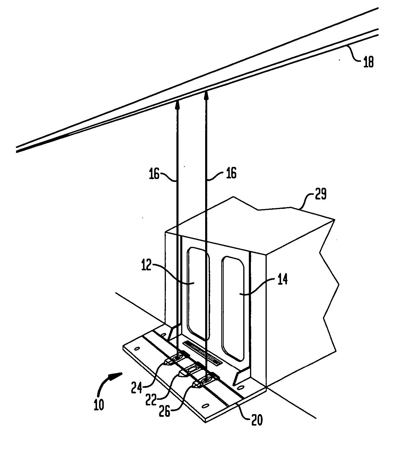
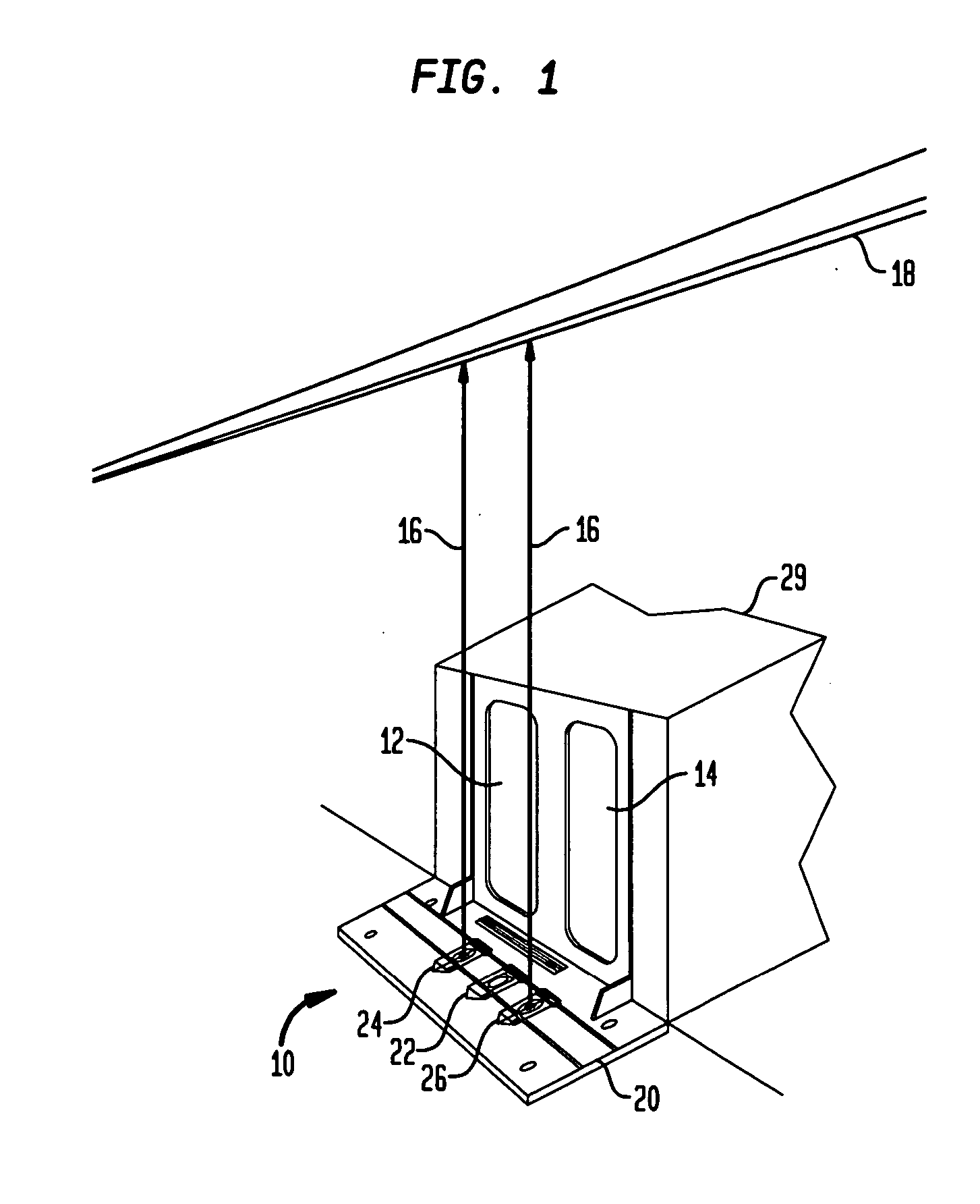
[0022] Referring now in specific detail to the invention, as shown in FIG. 1, there is illustrated an overall representation of an alignment arrangement 10 for calibrating semiconductor process tool equipment relative to two FOUP load ports 12, 14 through a laser beam projection 16 to an automated overhead track system 18, the latter of which was previously installed in a fabrication plant or facility. As explained in detail hereinbelow, the alignment arrangement 10 comprises a jig base plate 20 supporting a primary laser mount 22 and at least two secondary laser mounts or prism attachments 24, 26; one at each side of the primary laser mount 22. The alignment arrangement, and in essence, the jig base plate 20, is adapted to have the laser beams 16 projected to suitable reference points or locations on the overhead track system 18, such beams being projected from the secondary laser mounts or prism attachments 24, 26, respectively, and with the central laser mount being directed so a...


PUM


Abstract

An arrangement for aligning a semiconductor process tool to a track system, and a method which facilitates the calibration and alignment between a previously installed overhead transport system in a fabrication facility or plant for semiconductor wafers or integrated circuit components, and a plurality of load ports on a process tool for the semiconductor wafer or integrated circuit components, which is to be subsequently installed in the fabrication facility.

Description

BACKGROUND OF THE INVENTION [0001] 1. Field of the Invention [0002] The present invention relates to an arrangement for aligning a semiconductor process tool to a track system, and to a method which facilitates the calibration and alignment between a previously installed overhead transport system in a fabrication facility or plant for semiconductor wafers or integrated circuit components, and a plurality of load ports on a process tool for the semiconductor wafer or integrated circuit components, which is to be subsequently installed in the fabrication facility. [0003] The concept of providing methods and arrangement for aligning a load port on a process machine or tool employed in the fabrication of various products, such as semiconductor wafers or integrated circuit components in a highly precisely aligned manner is widely known and employed in the applicable technology. In this connection, in many instances the overhead transportation systems utilized for the delivery of the comp...

Claims


Application Information

Patent Timeline
IPC IPC(8): G01B11/00H01L21/00H01L21/677
CPCH01L21/67763H01L21/67259
Inventor DEGEORGE, JOSEPH P.YOUNG, ROBERT R. JR.
Owner GLOBALFOUNDRIES INC
Why Eureka
Try Eureka