Oil bath encoder seal

a technology of encoder seal and oil bath, which is applied in the direction of mechanical equipment, instruments, transportation and packaging, etc., can solve the problems of requiring additional expense and labor, and converting to inductive type sensors, and achieves compact size, low cost, and favorable use.

Inactive Publication Date: 2008-11-25
FEDERAL MOGUL WORLD WIDE
View PDF21 Cites 13 Cited by
  • Summary
  • Abstract
  • Description
  • Claims
  • Application Information

AI Technical Summary

Benefits of technology

[0011]Accordingly, the subject invention advantageously makes use of an encoder ring style target which is used on inductive sensor type assemblies and has become more favorable in use due to its lower cost, compact size, lightweight and durability as compared with the prior art tone ring style targets. However, the sensor used with the subject encoder ring is a variable reluctance (VR) type sensor which, according to the prior art, has been used before only in connection with a thicker tone ring style target. Thus, the subject invention unites an encoder ring style target with a variable reluctance type sensor to produce the signal used to calculate vehicle speed. This novel approach allows service operators to replace old style tone ring type targets with the newer, preferred encoder style ring when the oil bath seal is replaced on the vehicle.
[0012]According to another aspect of the invention, an oil bath seal is provided of the type for establishing a dynamic sealing interface between a rotating hub and a stationary spindle. The oil bath seal comprises a metallic carrier including a carbon steel flange. A flexible sealing element is fixedly joined to the carrier for establishing a fluid impervious seal against an opposing surface, such as a wear sleeve or the spindle per se. An annular encoder ring is fixed to the flange concentrically about the axis. The encoder ring has an exposed face comprising a plurality of magnetically polarized sectors alternating between North and South poles. A carbon steel flange includes a pilot feature for locating the encoder ring on the flange in a centered condition relative to the axis. Accordingly, the subject oil bath seal can be more rapidly produced, in that the pilot feature allows rapid locating and placement of the encoder ring on the flange in a perfectly centered condition.

Problems solved by technology

The rotating permanent magnet is often referred to as an encoder ring, and has never been used with the older-style VR sensor because the magnetic flux field produced by the encoder ring has been thought too weak to produce sufficient signal strength.
And while the tone ring style target designs have become somewhat disfavored because of their comparatively lower durability, thickness / weight and susceptibility to debris accumulation and corrosion, changing to an inductive type sensor would require the added expense and labor of also changing its inductive pickoff coil to the type used in an inductive-type sensor assembly.

Method used


Image

  • Oil bath encoder seal
  • Oil bath encoder seal
  • Oil bath encoder seal

Examples


Embodiment Construction

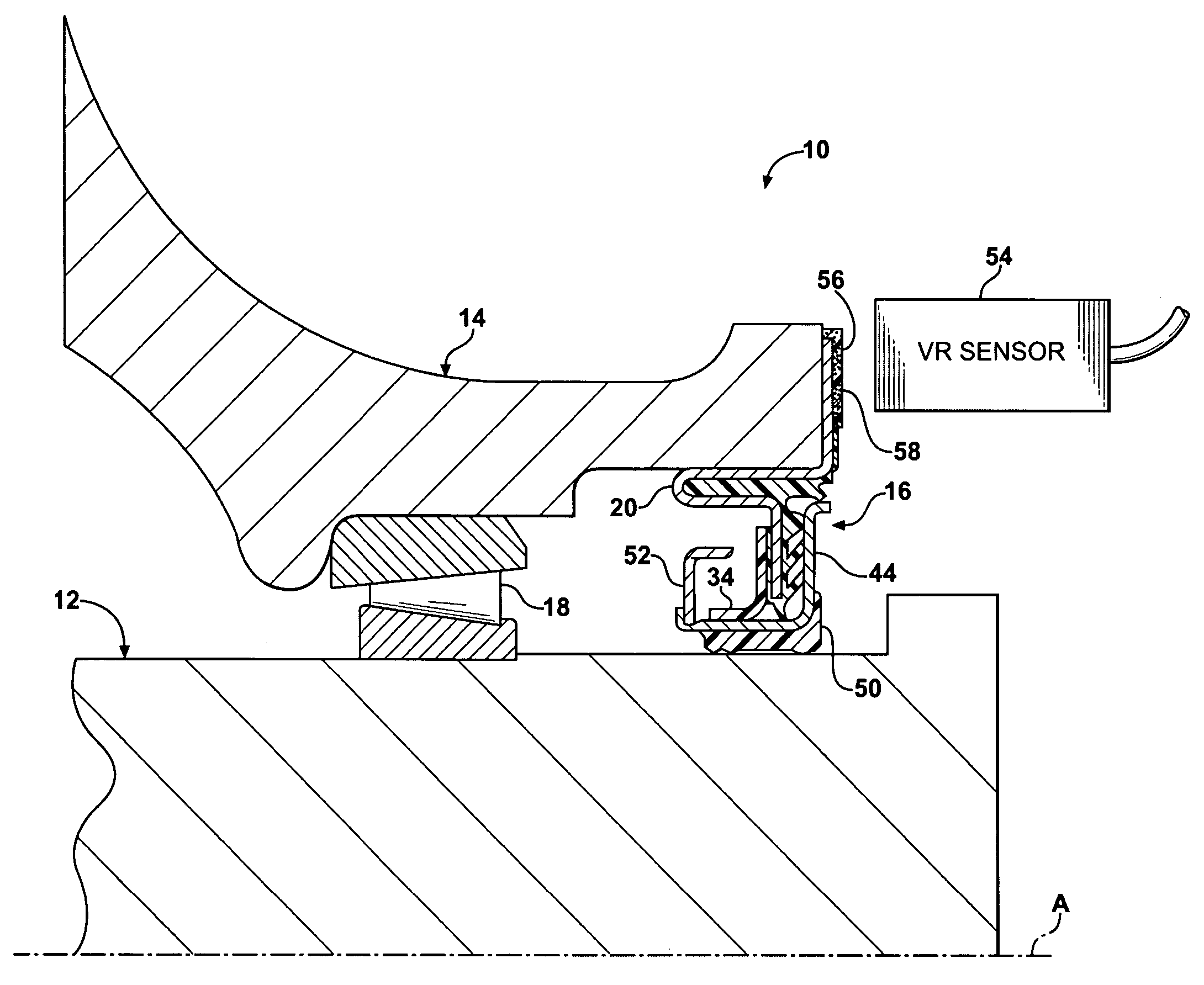
[0021]Referring to the Figures, wherein like numerals indicate like or corresponding parts through the several views, a simplified cross-sectional view of an oil lubricated rotating hub and stationary spindle assembly is generally shown at 10. The assembly 10, which may be of a truck axle-wheel type, includes a stationary axle or spindle, generally indicated at 12, and a rotating wheel hub, generally indicated at 14. The hub 14 is supported on the spindle 12 for rotation about a central axis “A”. In FIG. 1, only that half of the assembly 10 above the central axis “A” is depicted, it being understood that the lower half is a mirror image.

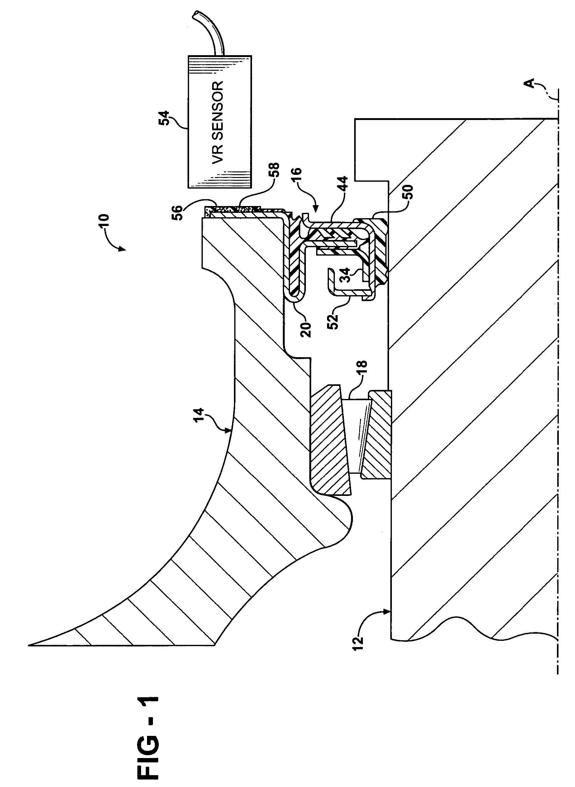
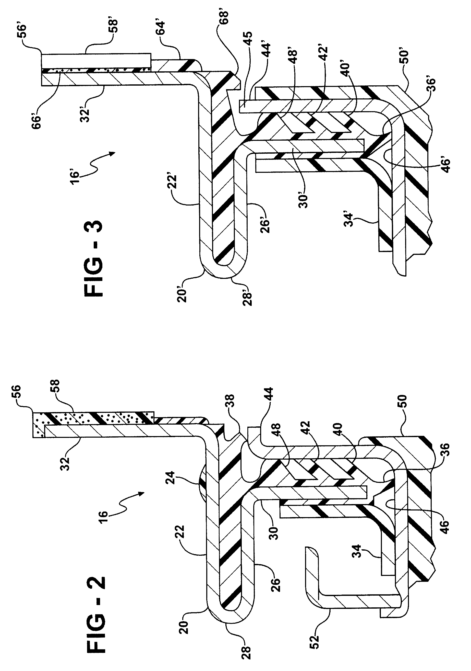
[0022]An oil bath seal, generally indicated at 16, establishes a dynamic sealing interface between the hub 14 and the spindle 12. In a typical arrangement, oil or other lubricating fluid will be contained in the interstitial space between the hub 14 and the spindle 12 on the left side of the oil bath seal 16 as view from FIG. 1, whereas the right han...


PUM


Abstract

An oil lubricated rotating hub (14) and stationary spindle (12) assembly includes an oil bath seal (16, 16′) for establishing a dynamic sealing interface between the hub (14) and spindle (12). A wheel sensor assembly includes a variable reluctance senor (54) targeted at an encoder ring (56, 56′) which is integrated into the oil bath seal (16, 16′). The encoder ring (56, 56′) is of the permanent magnet type including a plurality of magnetically polarized sectors alternating between North and South polarities. The use of an encoder style target (56, 56′) in combination with a variable reluctance sensor (54) enables improved slow speed sensing with relatively large air gap spacing between the exposed (58, 58′) of the encoder ring (56, 56′) and the head of the VR sensor (54). Furthermore, the encoder ring (56, 56′) enables use of less expensive, lighter materials for the oil bath seal carrier (20, 20′).

Description

BACKGROUND OF THE INVENTION[0001]1. Field of the Invention[0002]The subject invention relates generally to a vehicular wheel hub assembly including an integrated oil seal and speed sensor feature.[0003]2. Related Art[0004]Vehicle speed sensors integrated into a wheel assembly have many useful purposes. One common use for a speed sensor assembly is to cooperate with the vehicle anti-lock braking system. During a vehicle braking condition, a speed signal generated by pulsed electrical signals from the speed sensor assembly is sent to an on-board computer that responds to the drop in vehicle speed. If a wheel lock-up condition is anticipated, the computer directs a valve in the brake system to relieve or modulate the fluid pressure within the brake assemblies at the wheel thereby preventing an undesired wheel lock-up condition. When the computer determines that a lock-up condition is no longer imminent, the braking pressure is returned to normal operation.[0005]In the case of larger tr...

Claims


Application Information

Patent Timeline
Patent Type & Authority Patents(United States)
IPC IPC(8): F16C32/00G01P3/488
CPCF16C33/76F16J15/326G01P3/443G01P3/487F16C41/007F16C2326/02F16C41/00F16C41/04
Inventor TOTH, DAVID MGRECA, GERALD AANDERSON, MICHAEL J
Owner FEDERAL MOGUL WORLD WIDE
Why Eureka
Try Eureka