Ventilator including a control unit and human sensor

a control unit and sensor technology, applied in the field of ventilators, can solve the problems of waste of excessive power, difficult to hold at low flow rate, and take a long time in operation to exhaust moisture components absorbed in building materials, and achieve the effect of short tim

Active Publication Date: 2008-11-25
PANASONIC CORP
View PDF13 Cites 54 Cited by
  • Summary
  • Abstract
  • Description
  • Claims
  • Application Information

AI Technical Summary

Benefits of technology

[0010]Accordingly, a desired ordinary ventilation flow rate can be securely assured. For example, when the calculated flow rate determined from the room space and duct length is 60 cubic meters per hour, if the maximum flow rate of the exhaust fan motor is 100 cubic meters per hour, the flow rate is set at 60% by the flow rate adjusting unit, and the flow rate can be increased or decreased and adjusted by manipulating the flow rate adjusting unit when inspecting the flow rate after installation, so that desired ordinary ventilation flow rate can be obtained.
[0011]In the ventilator of the invention, the fixed flow rate operated by the signal from the human sensor is the maximum flow rate of the exhaust fan motor. It is hence possible to ventilate quickly in a short time.
[0012]In the ventilator of the invention, the exhaust fan motor is a direct-current motor. If the exhaust fan motor is an alternating-current motor, the flow rate can be generally lowered only to 70% of the maximum flow rate, but by using a direct-current motor, the flow rate can be lowered to about 30%. Hence, the low flow rate portion of exhaust fan motor can be controlled widely to 30 cubic meters, and power consumption can be saved while it is less likely to have effects of static pressure.
[0013]The ventilator of the invention has a wall switch built in the wall, and power switch is not disposed in the wall switch, but it has a selector 7a for selecting between automatic operation mode for automatically changing the ventilation flow rate by detection of the human sensor, and continuous operation mode for operating the exhaust fan motor continuously by force at specified ventilation flow rate. Either operation mode can be selected, and power on / off operation is not needed. Hence the exhaust fan motor is always operated in either mode, and the user can select by the wall switch either automatic operation mode by the human sensor when automatic operation is selected, or continuous operation for operating at specified flow rate when continuous operation is selected. Hence, ventilation is not interrupted by the usual manipulation by the user and ordinary ventilation operation can be conducted securely.
[0015]In the ventilator of the invention, the suction louver is rotatably installed. Hence, the detection range can be set freely regardless of condition of installation. Further, the user can freely set a desired detection range.
[0018]In the ventilator of the invention, the control unit, receiving a signal from the human sensor, measures the user staying time, and controls the ventilation flow rate during ventilation delay operation after the user leaves on the basis of the cumulative time. For example, if the human detection cumulative time is more than specified, fast ventilation operation can be presented for exhausting the high moisture state after bathing quickly and in a short time.

Problems solved by technology

In such ventilator, when adjusting the ventilator determined from the calculated flow rate and the actual flow rate after installation, the flow rate of fan motor is adjusted, for example, in two steps, and the adjusting interval is wide, and the flow rate may be set more than necessary, and excessive power may be wasted.
Meanwhile, when an alternating-current induction motor is used as fan motor, since the torque is small, it is hard to hold at low flow rate, and it is likely to have effects of static pressure by duct or the like.
If low flow rate operation during bathing in the bathroom is continued after the user leaves the bathroom, it takes a very long time in operation for exhausting moisture components absorbed in the building materials after use of bathroom.

Method used


Image

  • Ventilator including a control unit and human sensor
  • Ventilator including a control unit and human sensor
  • Ventilator including a control unit and human sensor

Examples


Embodiment Construction

[0026]A preferred embodiment of the invention is described below while referring to FIG. 1 to FIG. 5.

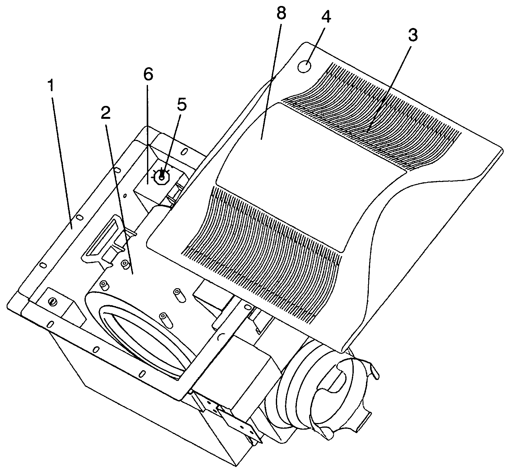
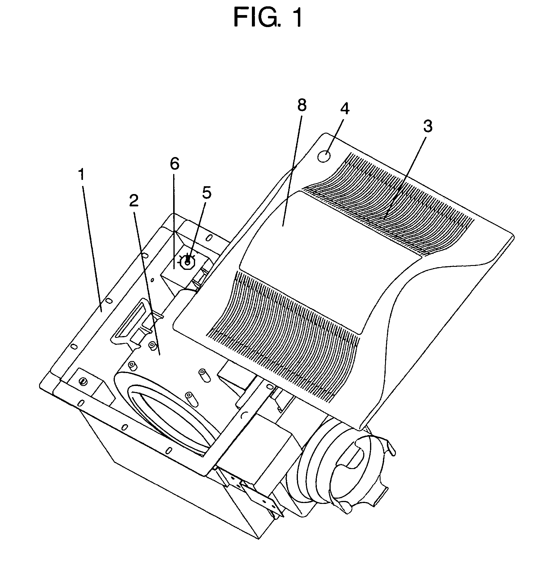
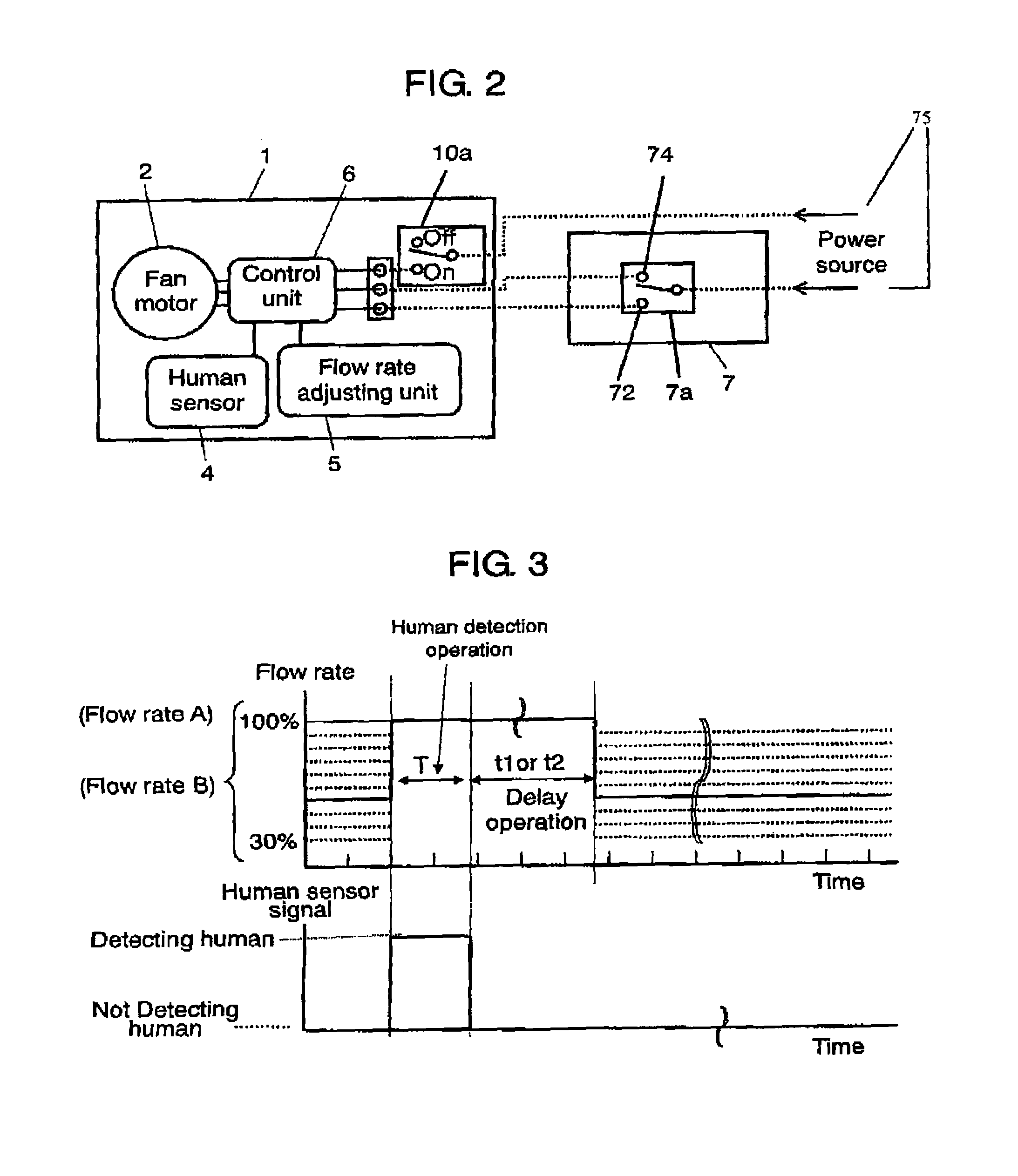
[0027]The ventilator of the invention comprises a ventilator main body 1, an exhaust fan motor 2 for exhausting room air by force, and a human sensor 4 for detecting the presence of human body. It further comprises a control unit 6 for controlling the fan motor 2 by receiving a signal from the human sensor 4, and a flow rate adjusting unit 5 for adjusting the ventilation flow rate by the exhaust fan motor 2. The control unit 6, when detecting a signal from the human sensor 4, operates the exhaust fan motor 2 for a specified time at fixed flow rate. While not detecting signal from the human sensor 4, it operates the exhaust fan motor 2 all the time at ventilated flow rate adjusted by the flow rate adjusting unit 5. During this ordinary operation, the flow rate may be adjusted by the flow rate adjusting unit 5 either steplessly or in multiple steps at small intervals.

[0028]Herein, by “...


PUM


Abstract

The invention presents a ventilator capable of obtaining an optimum flow rate required in ordinary ventilation. The ventilator comprises an exhaust fan motor for exhausting room air by force, and a human sensor for detecting the presence of human body. It further comprises a control unit for controlling the fan motor by receiving a signal from the human sensor, and a flow rate adjusting unit for adjusting the ventilation flow rate by the exhaust fan motor. The control unit, when detecting a signal from the human sensor, operates the exhaust fan motor for a specified time at fixed flow rate, and while not detecting, it operates the exhaust fan motor all the time at ventilated flow rate adjusted by the flow rate adjusting unit. During this ordinary operation, the flow rate may be adjusted by the flow rate adjusting unit either steplessly or in multiple steps at small intervals, and thereby a ventilator capable of obtaining an optimum flow rate required in ordinary ventilation can be presented.

Description

TECHNICAL FIELD[0001]The present invention relates to a ventilator for ventilating in order to exhaust moisture and odor generated by human behavior in living spaces especially bathroom and toilet.BACKGROUND ART[0002]This kind of ventilator is usually installed by calculating the ventilation rate from the specified number of times of ventilation, structure of house, and room space at the time of designing a house, and determining the model of ventilating apparatus in consideration of duct length and other conditions of installation work. In actual installation works, it is often required to adjust the air flow rate by inspecting the calculated air flow rate and actual air flow rate after installation. Accordingly, the ventilator main body is provided with an air flow rate adjusting unit capable of adjusting the air flow rate in two steps, such as flow rate 1 and flow rate 2, and the air flow rate is adjusted appropriately.[0003]FIG. 6 is a schematic wiring diagram of a conventional ...

Claims


Application Information

Patent Timeline
Patent Type & Authority Patents(United States)
IPC IPC(8): F24F7/007F24F11/02
CPCF24F7/06F24F11/0034F24F2007/001F24F11/30F24F2120/10F24F11/77F24F11/62
Inventor TAYA, HITOSHI
Owner PANASONIC CORP
Why Eureka
Try Eureka