Pulse finding apparatus and method

a technology of pulse finding and dial system, which is applied in the direction of distance measurement, instruments, and using reradiation, can solve the problems of ambiguity or difficulty in detecting on-line pulse samples, and degrade the detection performance of dial system

Active Publication Date: 2008-11-25
HARRIS CORP
View PDF3 Cites 14 Cited by
  • Summary
  • Abstract
  • Description
  • Claims
  • Application Information

AI Technical Summary

Problems solved by technology

This low signal / noise (S / N) ratio, when the gas of interest is present in the target scene, results in ambiguities or difficulties in detecting the ON-line pulse samples.
These ambiguities and difficulties degrade the detection performance of the DIAL system.

Method used


Image

  • Pulse finding apparatus and method
  • Pulse finding apparatus and method
  • Pulse finding apparatus and method

Examples


Embodiment Construction

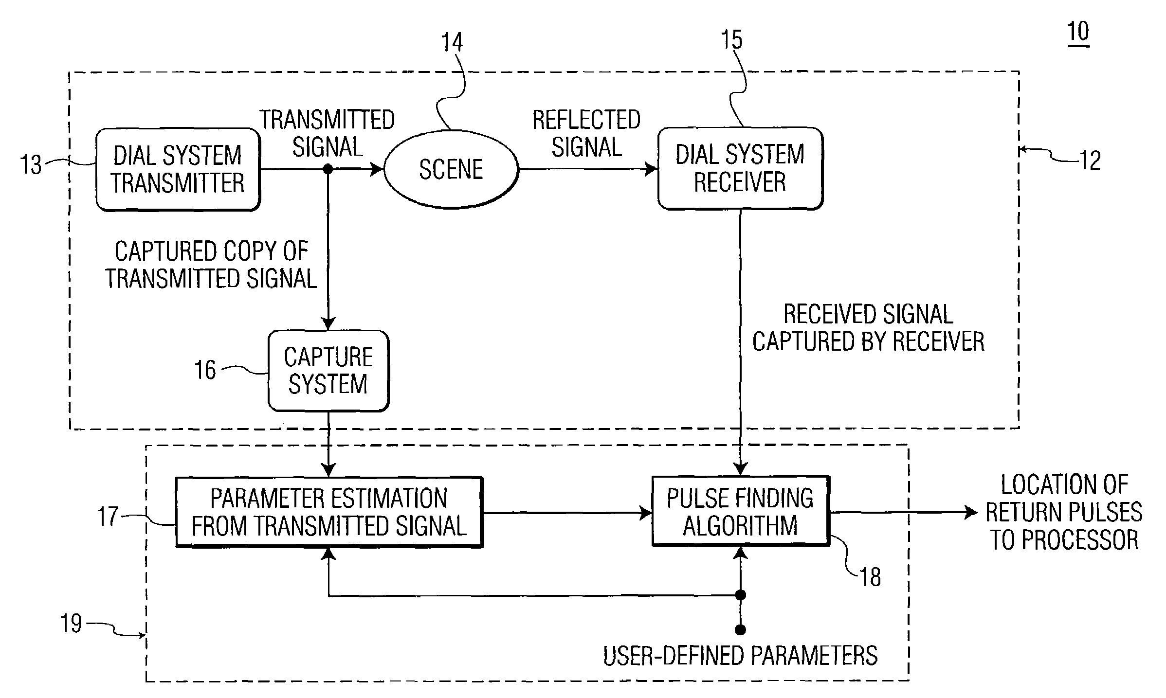
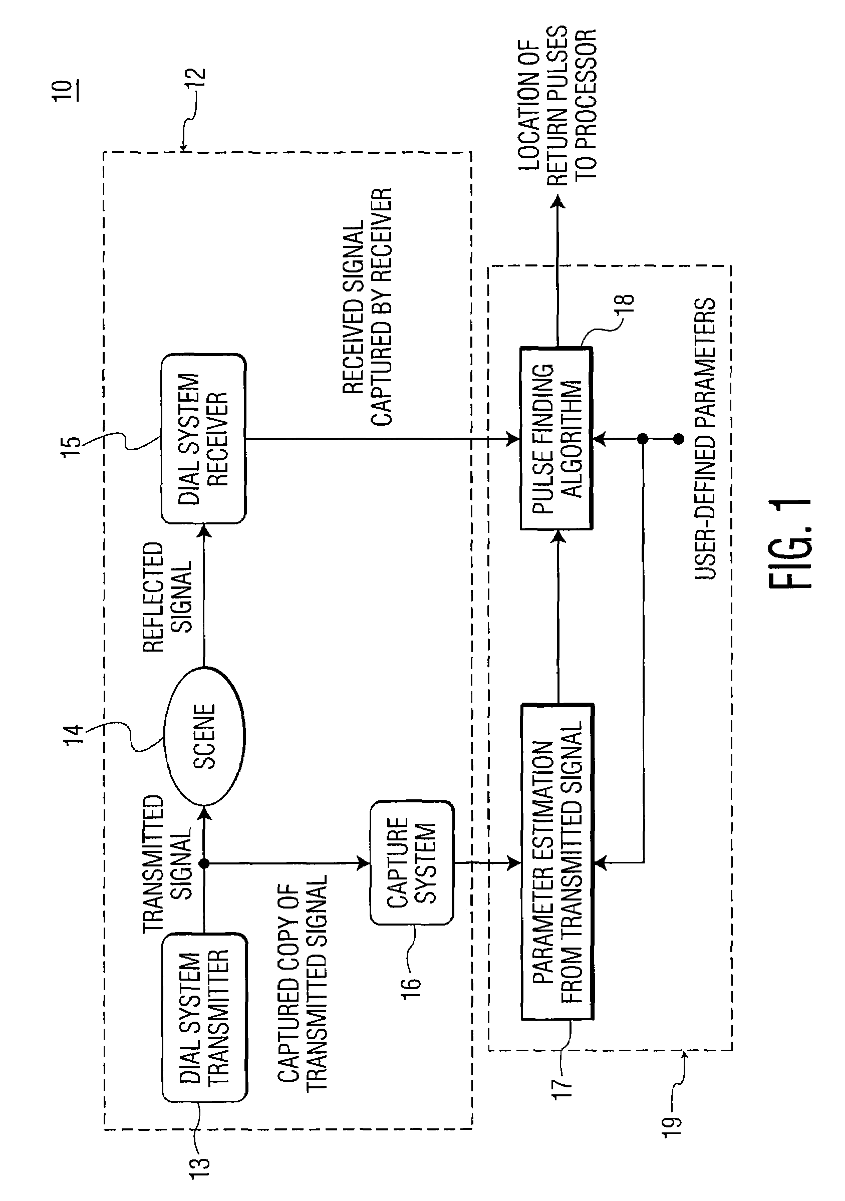
[0044]As will be explained, a method of the present invention captures and analyzes samples of received laser pulses, in addition to any other signal processing techniques used in the DIAL system. The present invention also provides a method that automatically determines the presence and location of a return pulse, without operator assistance.

[0045]It will be appreciated that this method may be used with any signal processing technique and is not limited to a DIAL system. It may be used in capturing and analyzing samples of a burst of pulses, in which the pulses in the burst have differing receive peak power levels and some of the pulses may have peak levels that are close to the noise level of the system.

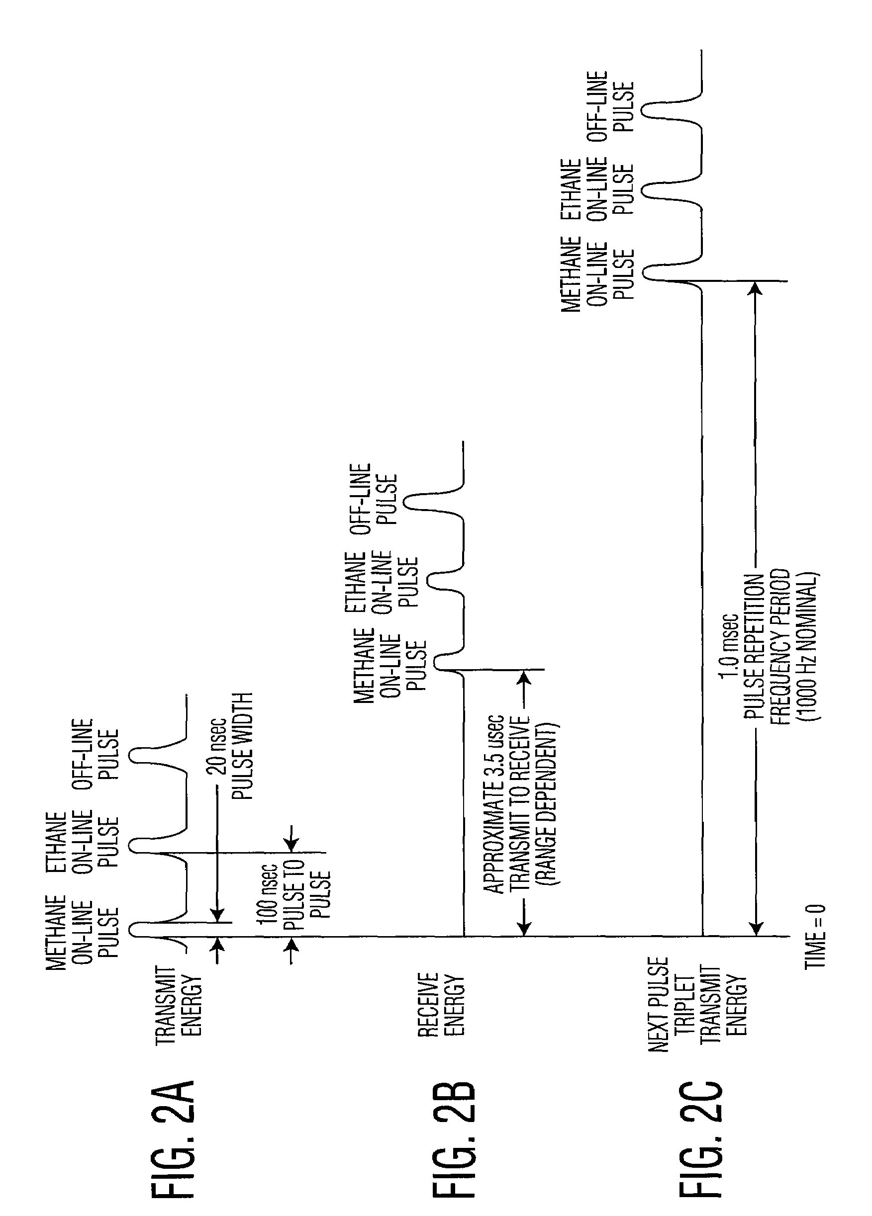
[0046]The present invention captures pulse sample data and determines where the samples corresponding to different laser returns are located in the captured pulse data. For situations where there is a gas present in the object scene, the low intensity of the reflected ON-line pulse...


PUM


Abstract

A method of finding a temporal location of a reflected pulse in a system for remotely measuring characteristics of a target scene. The method includes steps of: (a) transmitting a pulse burst of two or more pulses toward the target scene; (b) capturing a copy of the pulse burst transmitted in step (a); (c) measuring an inter-pulse separation between at least two pulses in the pulse burst captured in step (b); (d) receiving a signal reflected from the target scene; (e) determining a temporal location of a first pulse in the signal received in step (d); and (f) determining a temporal location of a second pulse in the signal received in step (d) based on the inter-pulse separation measured in step (c). Step (a) may include transmitting an OFF-line pulse and at least one ON-line pulse in the pulse burst toward the target scene from a differential absorption LIDAR (DIAL) system, where the OFF-line pulse and the ON-line pulse are combined pulses, each individually generated from a separate pulsed laser transmitter and each having a different wavelength.

Description

TECHNICAL FIELD[0001]The present invention relates, in general, to differential absorption LIDAR (DIAL) systems used to remotely measure characteristics of gases in the atmosphere. More specifically, the present invention relates to a system and method for locating laser pulses transmitted from a DIAL system and reflected back from a target scene.BACKGROUND OF THE INVENTION[0002]Differential absorption LIDAR (DIAL) systems may be used to remotely measure the chemical composition of gases in the atmosphere. These gases may be present in the atmosphere or they may originate from other sources, such as gas leaks stemming from natural gas pipelines.[0003]In an exemplary DIAL system, two lasers may be used. One laser may have a wavelength selected to coincide with a strong absorption feature of the gas to be detected. The other laser may have a wavelength selected in the wing (non-absorption region) of this absorption feature. The laser tuned to the absorption feature is referred to as t...

Claims


Application Information

Patent Timeline
Patent Type & Authority Patents(United States)
IPC IPC(8): G01C3/08
CPCG01S17/10G01S17/88G01S17/95Y02A90/10
Inventor LOPEZ, NORMAN A.LIPPERT, JOSEPH L.MCCONNELL, LISA E.
Owner HARRIS CORP
Why Eureka
Try Eureka