Discriminating natural fracture- and stress-induced sonic anisotropy using a combination of image and sonic logs

a sonic anisotropy and image technology, applied in the field of borehole geology and geophysics, can solve the problems of difficult interpretation, difficult interpretation of observed anisotropy, and inability to discriminate and achieve the effect of discriminating the relative effects of natural fracture- and stress-induced sonic anisotropy and a forward quantitative modeling techniqu

Inactive Publication Date: 2008-11-25
SCHLUMBERGER TECH CORP
View PDF23 Cites 27 Cited by
  • Summary
  • Abstract
  • Description
  • Claims
  • Application Information

AI Technical Summary

Benefits of technology

[0007]In accordance with another embodiment of the invention, apparatus for distinguishing fracture- and stress-induced sonic anisotropy comprises: a memory operable to store image data and sonic data associated with a borehole; circuitry operable to employ the sonic data to estimate at least one compressional and two shear moduli, and the dipole fast shear direction; circuitry operable to employ the image data to identify fracture type and orientation; circuitry operable to compute fast-shear azimuth and difference in slowness between the fast- and slow-shear due to geological fractures; and circuitry operable to identify depth zones with an elastic medium as being influenced by at least one of the presence of open natural fractures, closed natural fractures and non-equal principal stress effects.

Problems solved by technology

s]. However when both fracture and stress effects are present, or when the analysis of dispersion curves is difficult to interpret due to attenuation of high frequencies [Donald, A. et al., Advancements in acoustic techniques for evaluating natural fractures, 47th A
rety.], or when the symmetry axis of the anisotropic medium and the borehole axis are not aligned, the interpretation of the observed anisotropy becomes more challen
However, no practical technique exists for forward quantitative modeling of both natural fracture- and stress-induced sonic anisotropy in order to discriminate their relative effects.

Method used


Image

  • Discriminating natural fracture- and stress-induced sonic anisotropy using a combination of image and sonic logs
  • Discriminating natural fracture- and stress-induced sonic anisotropy using a combination of image and sonic logs
  • Discriminating natural fracture- and stress-induced sonic anisotropy using a combination of image and sonic logs

Examples


Embodiment Construction

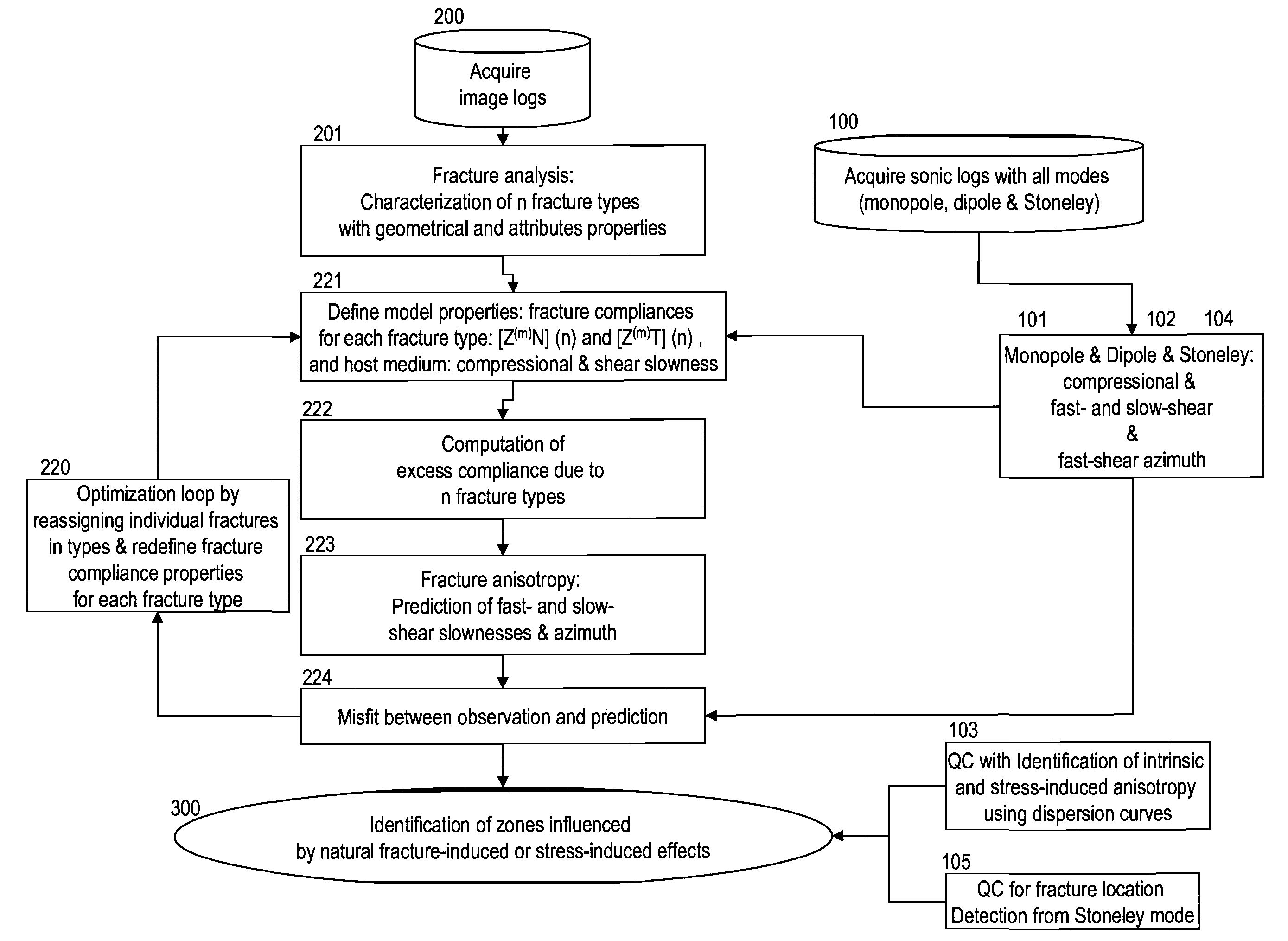
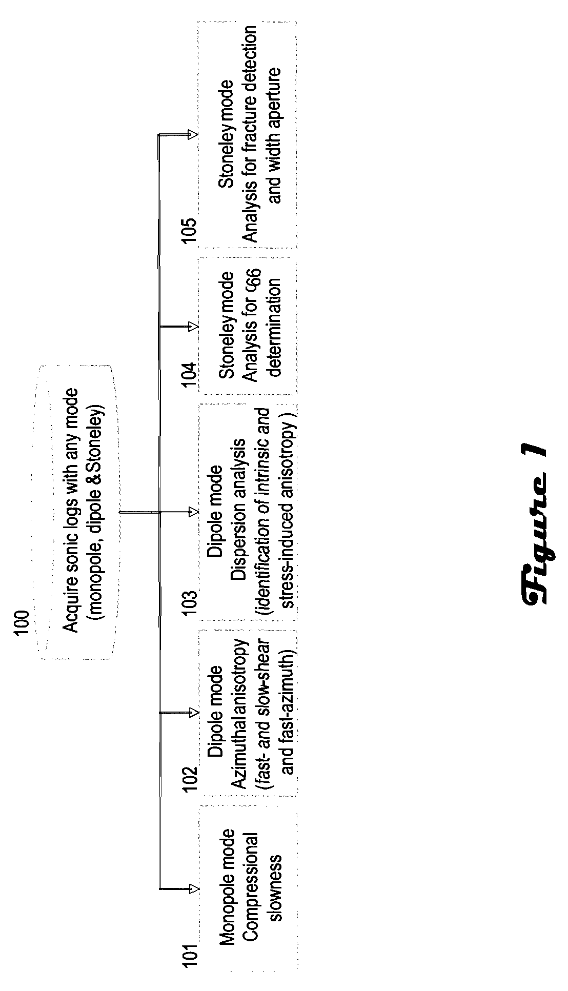
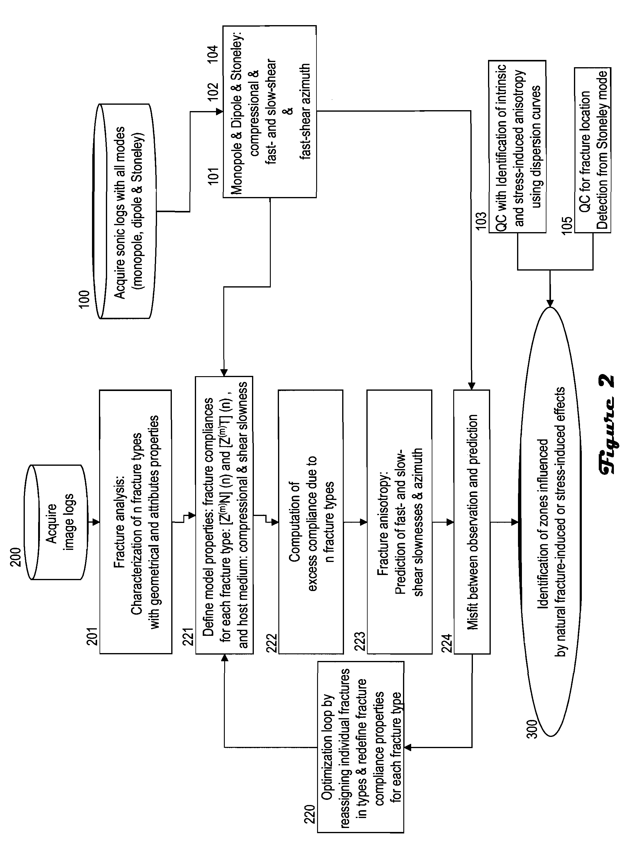
[0010]Referring to FIGS. 1 and 2, in an initial step (100), sonic logs are acquired with any one or combination of available modes, including, but not limited to, monopole, dipole and Stoneley. Monopole P- and S-waves, monopole Stoneley and cross-dipole shear sonic data associated with an anisotropic formation are used to estimate one compressional and three shear moduli. An orthorhombic formation with a vertical symmetry axis is characterized by three shear moduli: c44, c55 and c66.

[0011]The sonic logs acquired in step (100) are processed in preparation for identification and evaluation of sonic anisotropic slowness properties. As shown in step (101), monopole mode compressional slowness is identified. The compressional slowness from the monopole mode is used as an input in step (221). As shown in step (102), shear anisotropy is identified from the dipole mode data. In a vertical borehole, two vertical dipole shear moduli (c44 and c55) are directly estimated from azimuthal anisotro...


PUM


Abstract

Fracture- and stress-induced sonic anisotropy is distinguished using a combination of image and sonic logs. Borehole image and sonic logs are acquired via known techniques. Analysis of sonic data from monopole P- and S-waves, monopole Stoneley and cross-dipole shear sonic data in an anisotropic formation are used to estimate at least one compressional and two shear moduli, and the dipole fast shear direction. Fracture analysis of image logs enables determination of fracture types and geometrical properties. Geological and geomechanical analysis from image logs provide a priori discrimination of natural fractures and stress-induced fractures. A forward quantitative model of natural fracture- and stress-induced sonic anisotropy based on the knowledge of fracture properties interpreted from image logs allows the computation of the fast-shear azimuth and the difference in slowness between the fast- and slow-shear. The misfit between predicted and observed sonic measurements (i.e. fast-shear azimuth and slownesses) is then optimized in order to discriminate depth zones with an elastic medium as being influenced by the presence of open natural fractures, closed natural fractures and fractures induced by non-equal principal stress effects.

Description

CROSS-REFERENCE TO RELATED APPLICATIONS[0001]A claim of priority is made to U.S. Provisional Patent Application Ser. No. 60 / 825,298, filed Sep. 12, 2006, entitled FORWARD MODELING OF FRACTURE-INDUCED ANISOTROPY IN BOREHOLE SONIC DATA, which is incorporated by reference.FIELD OF THE INVENTION[0002]The present invention is generally related to the fields of borehole geology and geophysics, and more particularly to the identification and evaluation of depth zones having an elastic medium modified by either natural fracture- or stressed-induced effects.BACKGROUND OF THE INVENTION[0003]Oil and natural gas are extracted from subterranean formations by drilling boreholes into hydrocarbon-bearing zones, building a well completion, and then recovering the product. Various sensors are utilized in order to enhance both the creation of the borehole and the productivity of the completed well. For example, wireline and logging-while-drilling sonic tools are utilized to measure the dynamic elastic...

Claims


Application Information

Patent Timeline
Patent Type & Authority Patents(United States)
IPC IPC(8): G01V1/00
CPCG01V1/50
Inventor PRIOUL, ROMAIN C. A.DONALD, JOHN ADAMKOEPSELL, RANDOLPHBRATTON, TOM R.KAUFMAN, PETERSIGNER, CLAUDE
Owner SCHLUMBERGER TECH CORP
Why Eureka
Try Eureka