Transmission signal generating circuit and radio base station communication apparatus using the same

a technology of transmission signal and communication apparatus, applied in multiplex communication, power management, baseband system details, etc., can solve the problems of low control speed in transmission power limiting operation, inability to quickly limit the overall transmission power, and inability to quickly limit the change of power.

Inactive Publication Date: 2008-11-25
NEC CORP
View PDF9 Cites 4 Cited by
  • Summary
  • Abstract
  • Description
  • Claims
  • Application Information

AI Technical Summary

Benefits of technology

[0014]It is, therefore, a principal object of the present invention to provide a transmission signal generating circuit and radio base station communication apparatus which have a specific arrangement which can quickly limit overall transmission power while maintaining the transmission power of a specific transmission channel.

Problems solved by technology

In such a conventional technique, however, since the delay time is long in a control loop, high-speed control cannot be done.
As described above, therefore, in the conventional transmission power limiting scheme, the first problem is that since the powers of all the transmission channels are uniformly controlled in accordance with a total transmission power value, even the transmission power of a transmission channel which is preferably kept constant is controlled in the same manner as the remaining transmission channels.
The second problem is that since the power of a transmission channel is controlled by the radio base station controller 21 instead of the radio base station communication apparatus 22 itself, the control speed in transmission power limiting operation is low, and a quick change in power cannot be promptly limited.
However, there has not been disclosed any specific circuit arrangement associated with transmission power limitation.
If, therefore, the above technique is applied to a known radio base station communication apparatus, control is required through the radio base station communication apparatus, posing a problem similar to the second problem.
In addition, since transmission power control needs to be performed for each transmission channel, control for transmission power limitation is complicated.

Method used


Image

  • Transmission signal generating circuit and radio base station communication apparatus using the same
  • Transmission signal generating circuit and radio base station communication apparatus using the same
  • Transmission signal generating circuit and radio base station communication apparatus using the same

Examples


first embodiment

Operation of First Embodiment

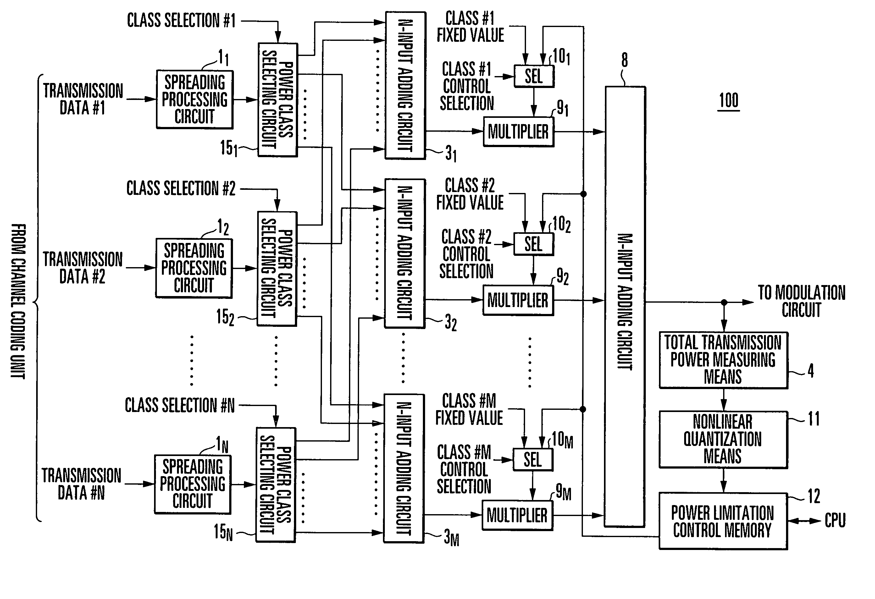
[0034]The operation of the radio base station communication apparatus according to the first embodiment of the present invention will be described next with reference to FIG. 1.

[0035]Output signals from the spreading processing circuits 11 to 1N which respectively spread N-channel transmission data are sent out to only the N-input adding circuits 31 to 3M corresponding to power classes selected from the M power classes defined in advance which are selected by the power class selecting circuits 151 to 15N using the respective class selection signals, and are added / combined for each power class.

[0036]The multipliers 91 to 9m functioning as power attenuators for the respective power classes multiply spread transmission signals added / combined for the respective power classes by multiplication coefficients. The M-input adding circuit 8 then adds the products for all the classes. The resultant data is sent out to a modulation circuit on the subsequent stage.

[0...

second embodiment

[0049]A radio base station communication apparatus according to the second embodiment of the present invention will be described next with reference to FIG. 4. FIG. 4 shows the arrangement of a CDMA radio base station communication apparatus according to the second embodiment of the present invention, and more specifically, a portion associated with a transmission signal generating circuit 100.

[0050]In this embodiment, as compared with the first embodiment described above, in order to reduce the circuit size, and more specifically, the number of N-input adding circuits, by achieving commonality of processing for each power class, commonality of class-specific adding processing circuits for all power classes is achieved by using a time-division multiplex frame format.

[0051]Referring to FIG. 4, transmission data #1 to #N which comprise N-channel symbol data and amplitude data and input from the channel coding unit are subjected to spreading processing in corresponding spreading proces...

third embodiment

[0060]A radio base station communication apparatus according to the third embodiment of the present invention will be described next with reference to FIG. 7. FIG. 7 shows the arrangement of a CDMA radio base station communication apparatus according to the third embodiment of the present invention, and more specifically, a portion associated with a transmission signal generating circuit 100.

[0061]The above second embodiment (see FIG. 4) has exemplified the case wherein the power limitation control memory 12 common to the respective power classes is used. However, as in the radio base station communication apparatus according to the third embodiment, power limitation control memories 121 to 12M may be provided for the respective power classes.

[0062]In this embodiment, as shown in FIG. 7, the power limitation control memories 121 to 12M are provided for the respective power classes between a nonlinear quantization means 11 and selectors 101 to 10M for the respective power classes.

[00...


PUM


Abstract

A transmission signal generating circuit in a radio base station that employs spread processing circuits in order to output spread transmission signals. The signal generating circuit further contains power class selecting circuits, which categorize spread transmission signals into power classes, a first adding circuit, which combines these signals, multipliers, which adjust transmission power of these signals for respective power classes, and a second adding circuit, which combines these signals. The circuit measures and quantinizes the total transmission power to output a power level. A power limitation control memory outputs a multiplication coefficient representing the power class for which transmission power control. Selectors in the circuit select when this control is permitted for a given power class and output this information to the multiplier corresponding to the class. When this control is inhibited for the class, a multiplication coefficient is formed from a predetermined value, and output to the corresponding multiplier.

Description

BACKGROUND OF THE INVENTION[0001]The present invention relates to a CDMA (Code Division Multiple Access) radio communication technique and, more specifically, a transmission power limiting technique of limiting the transmission power of a radio wave transmitted from a radio base station apparatus to a terminal to an allowable average power or less, i.e., a transmission signal generating circuit and a radio base station communication apparatus using the circuit.[0002]In a mobile communication system such as a cellular phone system, a radio base station communication apparatus uses a CDMA spread spectrum technique of performing radio communication between a base station and a terminal by using an information signal obtained by time-division multiplexing of signals spread by orthogonal codes.[0003]In such a CDMA scheme, in order to suppress waveform distortion in a transmission power amplifier within a tolerance limit, the transmission power must be limited to prevent a radio wave from...

Claims


Application Information

Patent Timeline
Patent Type & Authority Patents(United States)
IPC IPC(8): H04L27/00H04B1/707H03G3/30H04B1/04H04B7/005H04B7/26H04J13/00H04W52/04H04W52/34
CPCH04W52/34H04B2201/70706
Inventor ATSUTA, HIROSADA
Owner NEC CORP
Why Eureka
Try Eureka