
Specified object detection apparatus

a technology of object detection and object detection, which is applied in the field of specified object detection apparatus, can solve the problems such as the requirement for real-time execution of the process of detecting a human face in an image on a device such as a portable telephone having a machine specification not comparatively high-sophisticated, and achieve the effect of improving the accuracy of the final judgment using the judgment value, and ensuring the accuracy of the final judgmen

Active Publication Date: 2008-11-25
ORMON CORP +1
View PDF8 Cites 16 Cited by
  • Summary
  • Abstract
  • Description
  • Claims
  • Application Information

AI Technical Summary

Benefits of technology

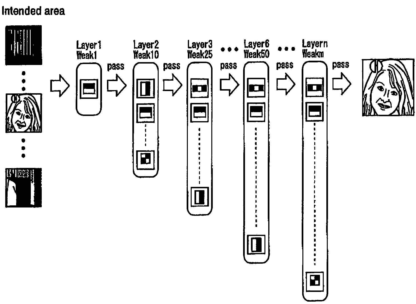
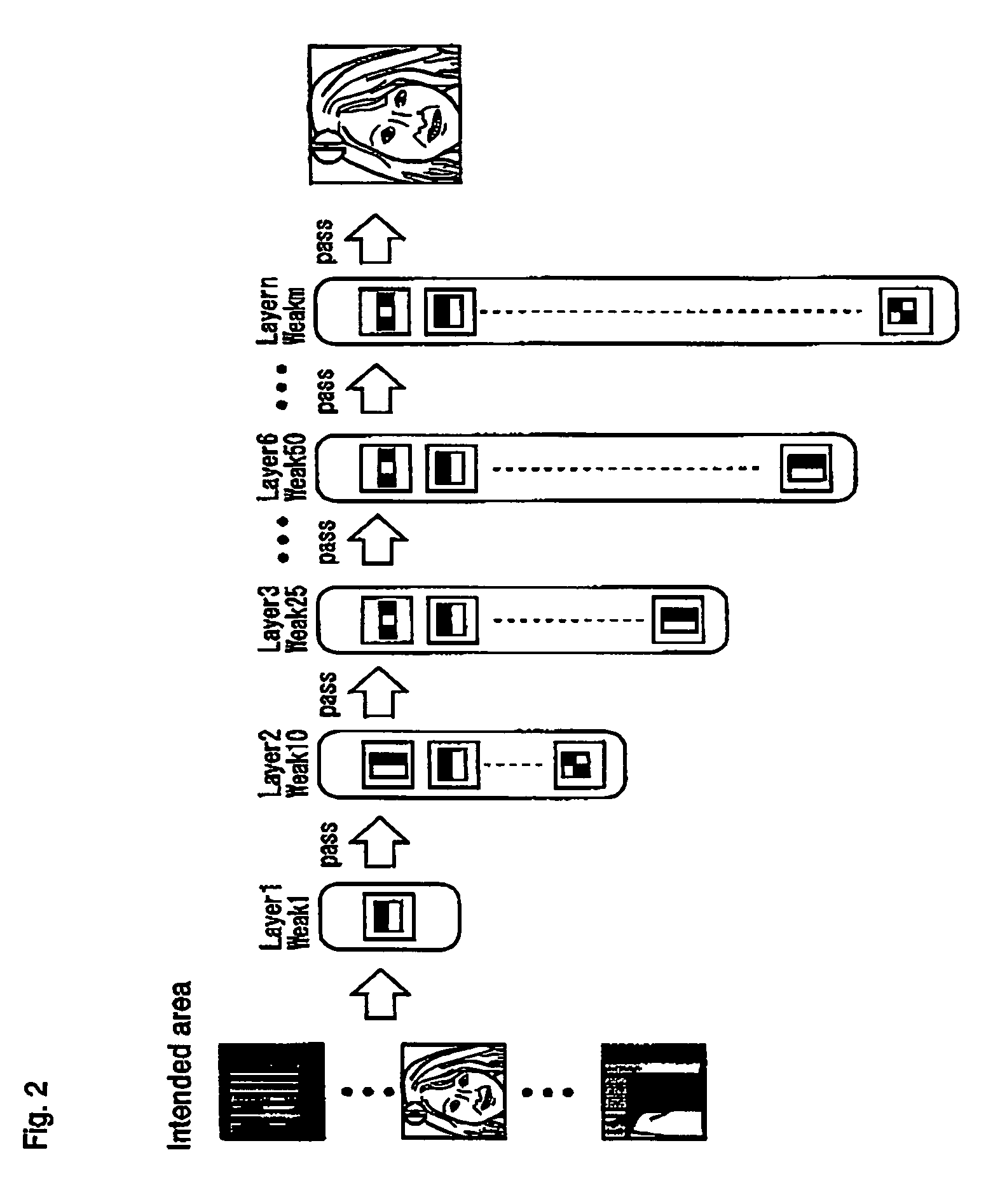
The invention provides a device for quickly and accurately detecting whether a human face is included in a given image. The device comprises a storage part, a calculation part, and a judging part. The storage part stores various judgment values for features such as the average, total, and distribution of pixels in an image. The calculation part calculates features for each pixel in an image and combines them to create a feature for the intended area. The judging part uses these features and corresponding judgment values to determine if a specified object is included in the intended area. The device can access area pattern information to define the partial area of an image and use different types of values and inputs for the calculation process to improve accuracy. The control part sets features and applies them to the judging part to acquire a sufficient number of judgment results. Overall, the device allows for faster and more accurate detection of human faces in images.

Problems solved by technology

Currently, however, the process of detecting a human face in an image is required to be executed in real time on a device such as a portable telephone having a machine specification not comparatively highly sophisticated.

Method used


Image

  • Specified object detection apparatus
  • Specified object detection apparatus
  • Specified object detection apparatus

Examples


first embodiment

[Principle]

[0108]The conventional face detection technique used with the face detection device 4 is explained above. Next, an explanation is given about a modified process of the face detection technique used with the face detection device 4a according to a first embodiment of the invention. Specifically, the process not described below is executed the same way as the process of the face detection technique described above.

[0109]In the conventional face detection technique, a simple arithmetic model is assumed to calculate a threshold value for the face rectangle 1 of each pattern. An actual shape of the histogram of the differential value and the number of face image samples and non-face image samples, therefore, has not been assumed. In the case of the face rectangle 1 illustrated in the uppermost portion in FIG. 6, for example, the feature around the left and right eyes is calculated as a feature of the first feature area, while the feature around the nose and the left and right ...

second embodiment

[Principle]

[0151]Next, the principle of the face detection technique applied to a face detection device 4b according to a second embodiment of the invention is explained. The description that follows deals with the difference from the face detection technique used in the first embodiment.

[0152]According to the first embodiment, the abscissa of the histogram (FIG. 9) is segmented into sections at specified intervals, after which each section is assigned a judgment value of “0” or “1”. According to the second embodiment, in contrast, each section is assigned a judgment value in real number. FIG. 15 is a diagram showing an example of the judgment value assigned to each section of the histogram according to the second embodiment. In the second embodiment, the judgment value indicates the degree of the probability or the very probability that the image distributed in the section of the corresponding differential value is a face image. Specifically, the judgment value in the first embodim...


PUM


Abstract

Unlike in the prior art in which the correspondence between a feature and a judgment value in an intended area is obtained by a single threshold value, the correspondence of the judgment value is obtained independently for each feature by use of a look-up table or the like. This makes it possible to achieve an accurate correspondence between the judgment value and the feature and thus to improve the high processing accuracy. Also, in the prior art, the judgment is repeated several times to secure the accuracy of the judgment and based on the total result thereof, the final judgment is made. Since the accuracy of each process is improved, however, the number of times the judgment is repeated is reduced for a higher processing speed.

Description

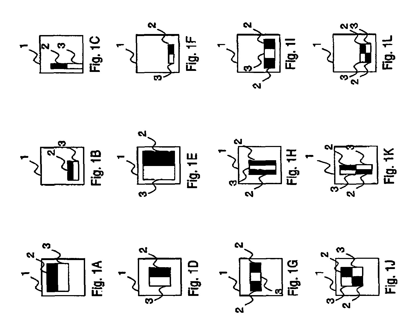
BACKGROUND OF THE INVENTION[0001]1. Field of the Invention[0002]The present invention relates to a technique effectively applicable to an apparatus and a method for detecting from a picked-up image a specified object or a part of the object such as a man, an animal or any other physical object included in the particular image.[0003]2. Description of the Background Art[0004]A conventional technique is available for detecting a specified object or a part of the object such as a man, an animal or any other physical object included in a picked-up image. An example of this conventional technique is to detect a human face from a picked-up image (See Paul Viola, Michael Jones, “Robust Real-Time Object Detection” SECOND INTERNATIONAL WORKSHOP ON STATISTICAL AND COMPUTATIONAL THEORIES OF VISION-MODELING, LEARNING, COMPUTING, AND SAMPLING VANCOUVER, CANADA, Jul. 13, 2001 (hereinafter referred to as Non-patent Reference 1)).[0005]In Non-patent Reference 1, a specified rectangle (hereinafter re...

Claims


Application Information

Patent Timeline
Patent Type & Authority Patents(United States)
IPC IPC(8): G06K9/00A61B1/04G06T1/00G06K9/62G06T7/00
CPCG06K9/00228G06K9/6257G06V40/161G06V10/7747G06F18/2148
Inventor AI, HAIZHOUHUANG, CHANGWU, BOLAO, SHIHONG
Owner ORMON CORP
Learn More