
Automatic cord length measuring device

a measuring device and cord technology, applied in the direction of measuring wheels, measuring apparatus for force/torque/work measurement, instruments, etc., can solve the problems of insufficient space to lay out such materials, inaccuracy, and inability to measure the length of elongated materials. , to achieve the effect of accurate measurement of the length of elongated materials

Inactive Publication Date: 2008-12-02
RICHARDSON SHANE D
View PDF21 Cites 11 Cited by
  • Summary
  • Abstract
  • Description
  • Claims
  • Application Information

AI Technical Summary

Benefits of technology

[0012]In view of the foregoing disadvantages inherent in the prior art, it has been observed that there is need for

Problems solved by technology

However, while a tape measure works great with rigid materials and fixed distances, it does not do so well with non-rigid materials such as rope, wire, cable, tubing and the like.
This can be a source of inaccuracy.
Also, on many jobsites, there is not enough room to lay such material out.
All of these difficulties can lead to costly mistakes if material is cut to a wrong dimension.
The Jin et al. device, unfortunately, is not designed for portability and cannot be held by hand.
The Shaw device is not easily portable and is not designed to be conveniently and comfortably held by hand.
Also, the Shaw device does not also incorporate an optical sensing mechanism.
In addition to the aforementioned prior art, the Smart et al. design is not suitable for hand-held portability and also does not include an optical sensing mechanism.
In addition to the aforementioned prior art, the Haglöf design is not suitable for hand-held portability and also does not include an optical sensing mechanism.
None of the prior art particularly describes a portable device that utilizes mechanical and optical readers to accurately measure the length of an elongate substrate, such as rope, cord, chain, etc.

Method used


Image

  • Automatic cord length measuring device
  • Automatic cord length measuring device
  • Automatic cord length measuring device

Examples


Embodiment Construction

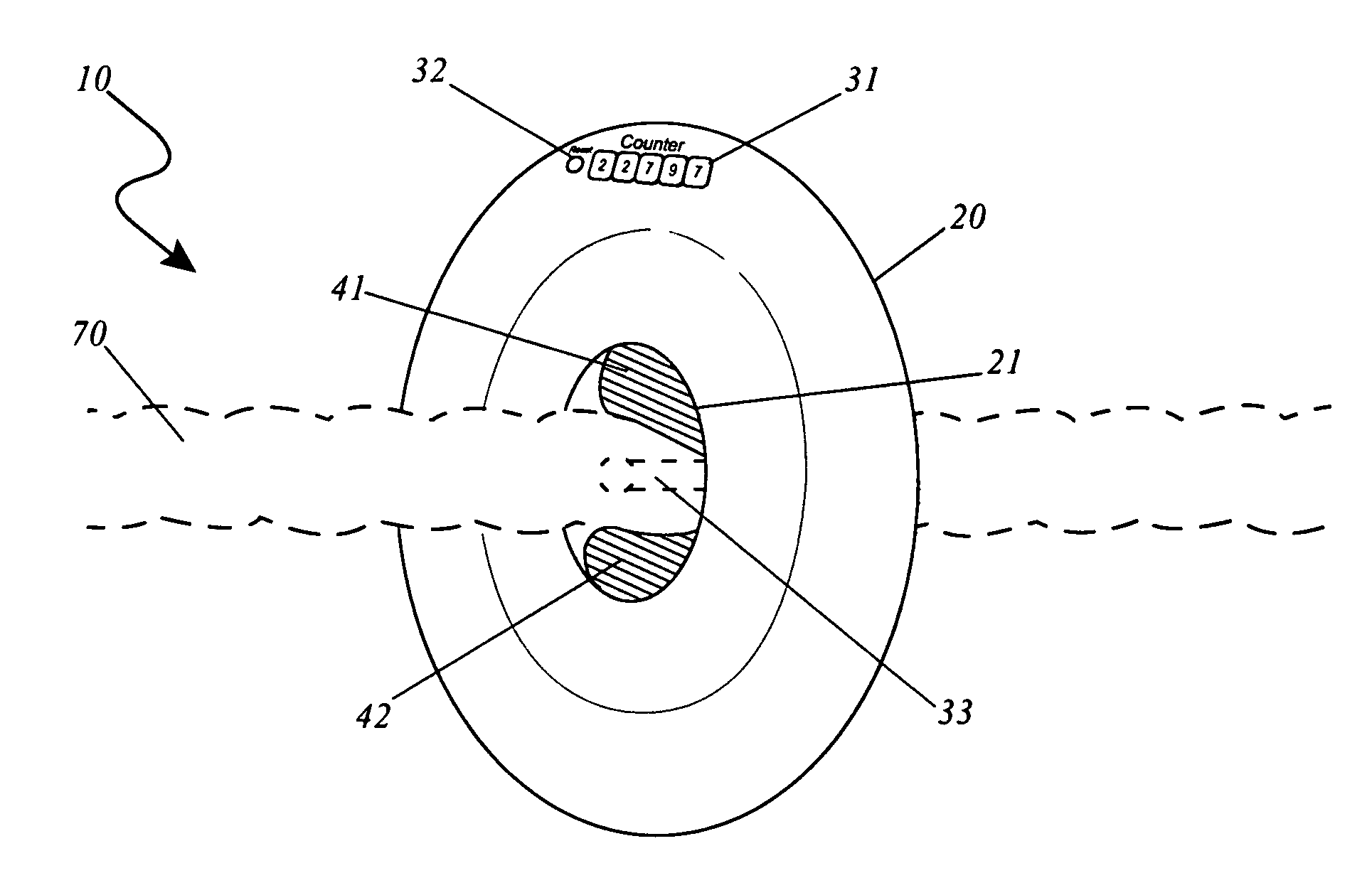
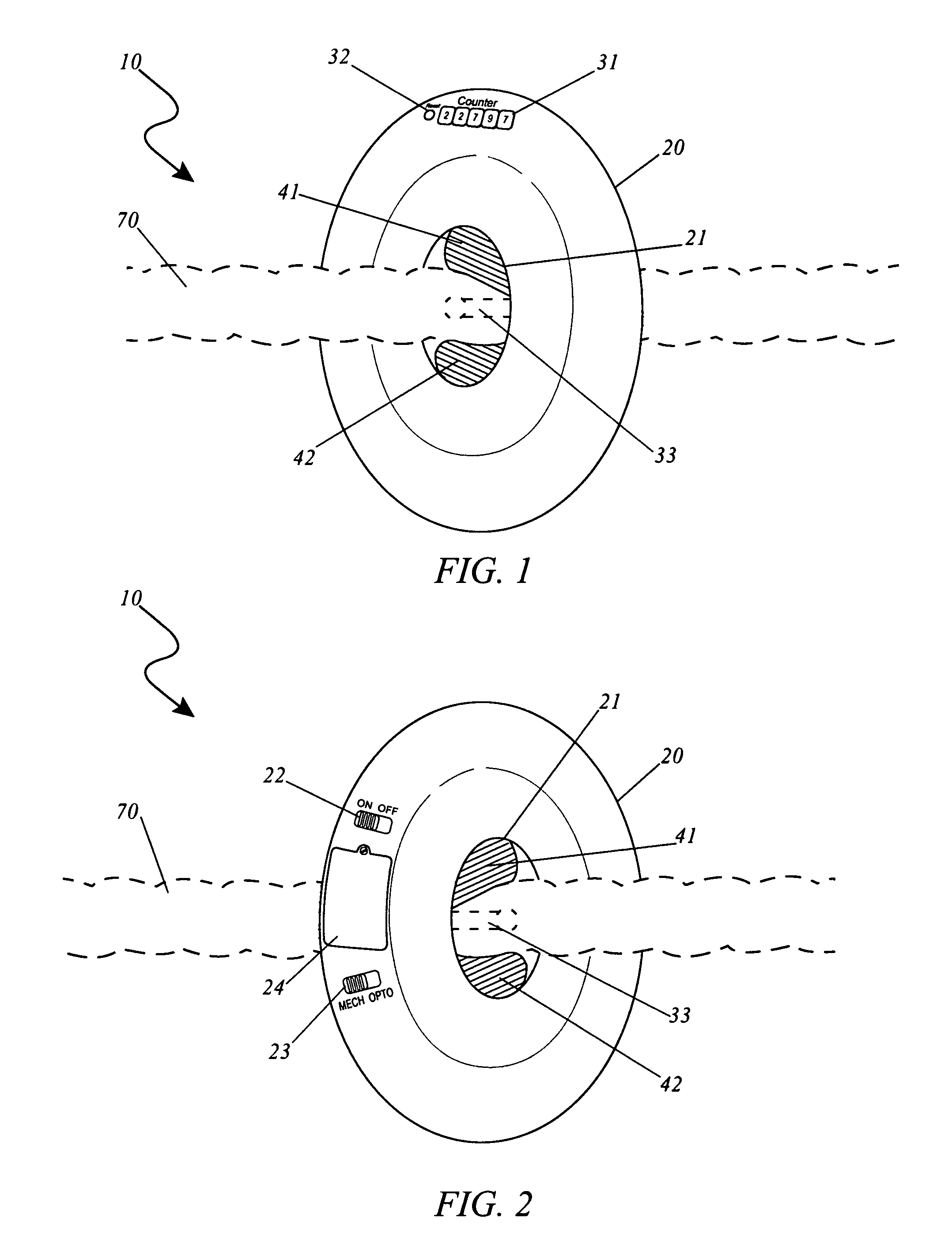
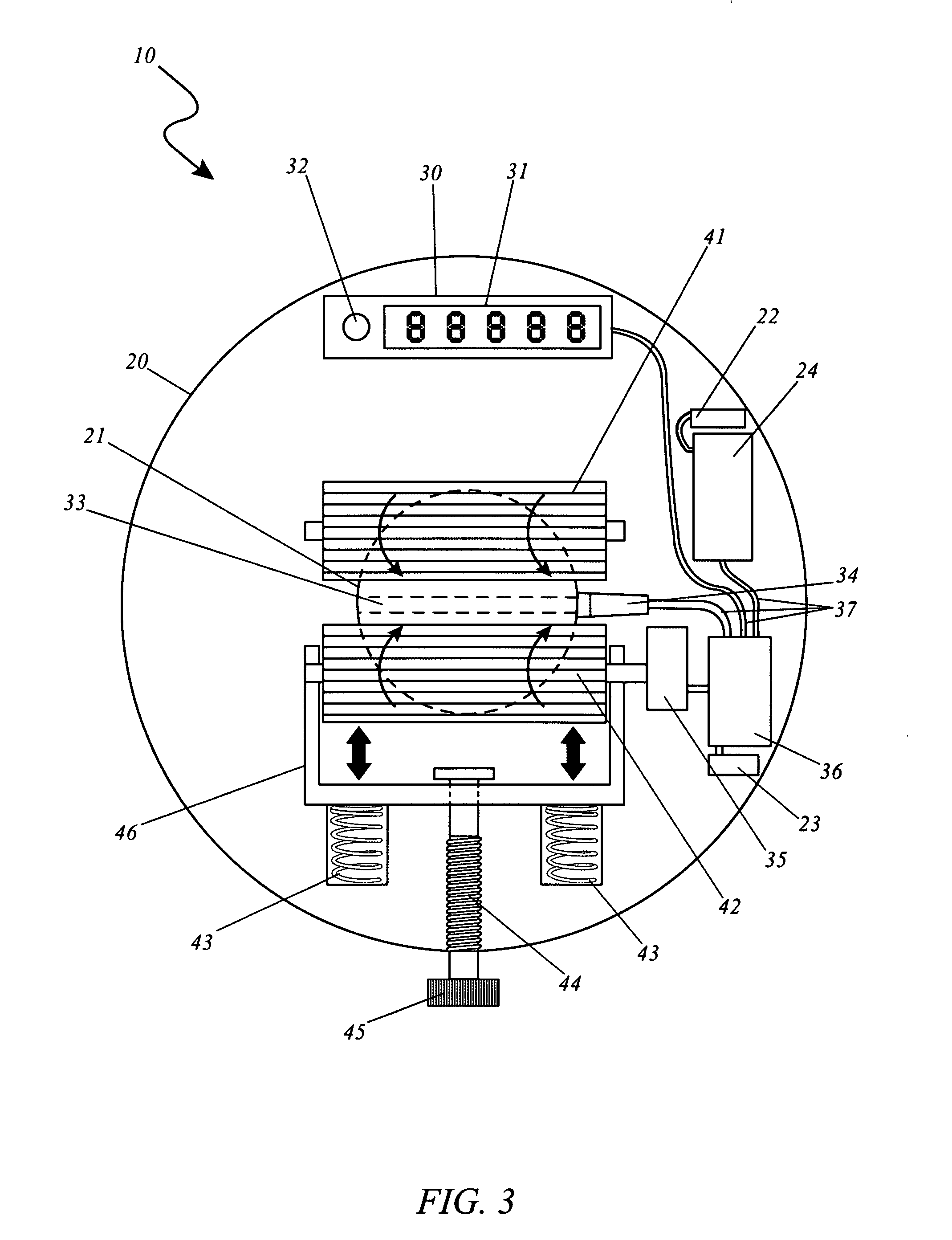
[0033]The best mode for carrying out the invention is presented in terms of its preferred embodiment, herein depicted within FIGS. 1 through 4. However, the invention is not limited to the described embodiment and a person skilled in the art will appreciate that many other embodiments of the invention are possible without deviating from the basic concept of the invention, and that any such work around will also fall under scope of this invention. It is envisioned that other styles and configurations of the present invention can be easily incorporated into the teachings of the present invention, and only one particular configuration shall be shown and described for purposes of clarity and disclosure and not by way of limitation of scope.

[0034]The terms “a” and “an” herein do not denote a limitation of quantity, but rather denote the presence of at least one of the referenced items.

[0035]The present invention describes an apparatus and method for an automatic cord length measuring dev...


PUM

PropertyMeasurementUnit
Lengthaaaaaaaaaa
Diameteraaaaaaaaaa
Diameteraaaaaaaaaa

Abstract

An apparatus that accurately measures rope, wire, tubing and other materials is herein disclosed. A variety of different-sized models would possess different sized openings. One model with a one-inch opening would be used to measure small wire and cable. Another model with approximately a 3-inch opening would be used for larger electrical cables, rope, tubing and the like. An even large model would be available for measuring ductwork, hoses, and other large diameter material. As the material is pulled through the opening, an optical sensor, similar to that used on an optical computer mouse, accurately measures the material to the fraction of an inch. A mechanical sensor, utilizing a guide wheel is also envisioned. The length is displayed on a digital readout on the perimeter of the invention that is provided with a power button, reset button and the like. It is envisioned that various attachments such as a belt loop, a spool attachment and other items to increase the versatility of the invention would also be provided.

Description

RELATED APPLICATIONS[0001]The present invention was first described in and claims the benefit of U.S. Provisional Application No. 60 / 774,042, filed Feb. 17, 2006, the entire disclosures of which are incorporated herein by reference.FIELD OF THE INVENTION[0002]The present invention relates generally to a system and method incorporating an apparatus to accurately measures rope, wire, tubing and other non-rigid material and, more particularly, to the measuring means being both mechanical and optical reader.BACKGROUND OF THE INVENTION[0003]One of the most common tools found in toolboxes of contractors and do-it-yourselfers is the tape measure. It is used in all stages of a project from the beginning planning stages, through detailed design, construction and final inspection. It provides extremely accurate measurements at a minimal cost. However, while a tape measure works great with rigid materials and fixed distances, it does not do so well with non-rigid materials such as rope, wire, ...

Claims


Application Information

Patent Timeline
IPC IPC(8): G01B3/12B26D7/28G01B5/04
CPCB65H61/00G01B3/12G01B5/043G01B11/043B65H2701/31Y10T83/858
Inventor RICHARDSON, SHANE D.
Owner RICHARDSON SHANE D
Learn More