
Lighting fixture

a technology of light fixture and light source, which is applied in the field of light source, can solve the problems of increasing the cost of led lamps, soft light emitted from led lamps, and single led piece not providing sufficient light intensity, so as to achieve soft illumination and save costs

Inactive Publication Date: 2008-12-02
SHENG CHEN KENG
View PDF4 Cites 15 Cited by
  • Summary
  • Abstract
  • Description
  • Claims
  • Application Information

AI Technical Summary

Benefits of technology

The solution allows for cost-effective soft illumination using fewer LEDs, as the light guide bar and reflectors enhance light distribution, making a single LED or a few LEDs sufficient for satisfactory illumination.

Problems solved by technology

However, for illumination purpose, a single piece of LED does not provide sufficient intensity of light.
However, using a number of LEDs relatively increases the cost of the LED lamp.
Moreover, light directly emitted from a LED is not soft.

Method used


Image

  • Lighting fixture
  • Lighting fixture
  • Lighting fixture

Examples


Embodiment Construction

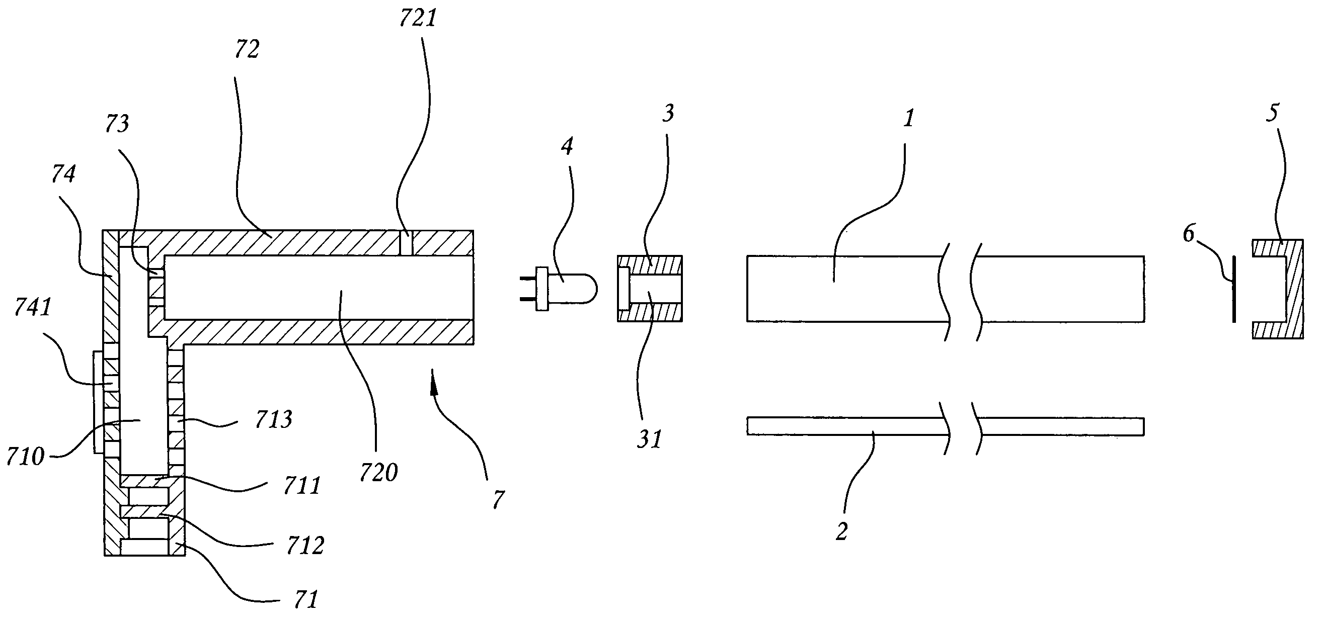
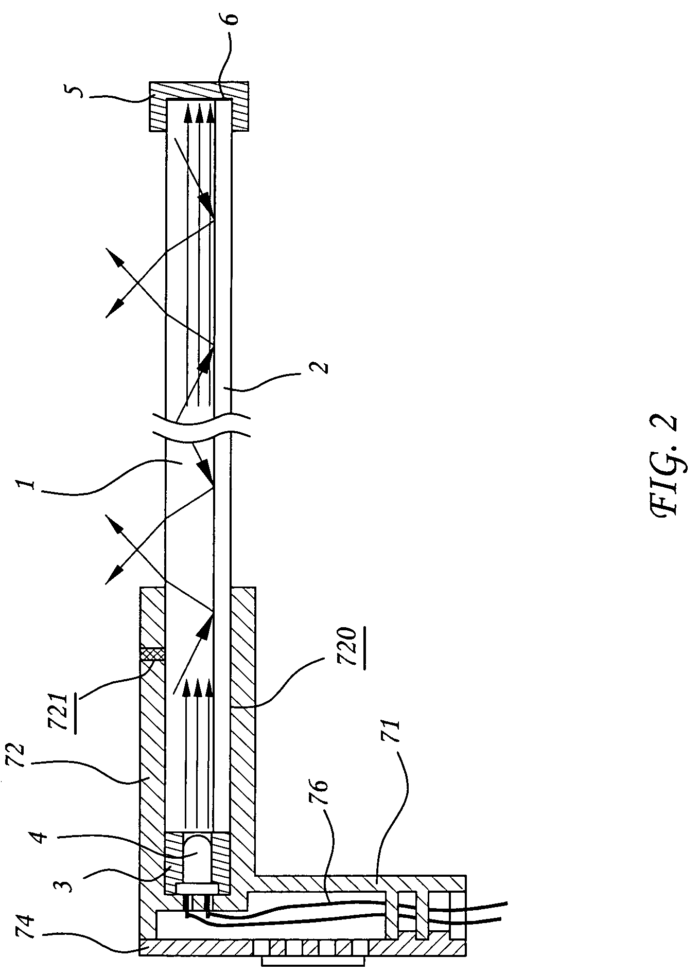
[0026]Referring to FIG. 1, a lighting fixture in accordance with one preferred embodiment of the present invention is shown comprised of a light guide bar 1, a first reflector 2, a socket 3, a light emitting device 4, a cap 5, a second reflector 6, and a connector 7.

[0027]The light guide bar 1 is a long bar made out of an optical material that allows light to pass and guides light, having a cross section of a predetermined shape, for example, circular shape in FIG. 4 or hexagonal shape in FIG. 5. The light guide bar 1 can be made having a rough outer surface 11 that shows a pattern of teeth (see FIG. 6), raised portions or cones (not shown). The rough outer surface 11 provides a function of refracting light in different directions.

[0028]The first reflector 2 is formed of a light reflecting film or sheet material, bonded to a part of the outer surface of the light guide bar 1 (see FIGS. 4˜6).

[0029]The first reflector 2 can be formed integral with the outer surface of the light guide ...


PUM


Abstract

A lighting fixture is disclosed to include a light guide bar, a connector holding a LED at a first end of the light guide bar, and a first reflector and a second reflector respectively covered on a part of the periphery and a second end of the light guide bar to reflect light from the LED out of the light guide bar. The connector has a barrel at the first end thereof that accommodates one end of the light guide bar and the LED, an accommodation space at the second end that accommodates electronic components, and a detoured wire path that guides electric wires of the LED out of the connector and prevents disconnection of the electric wires from the LED. A second LED may be attached to the second end of the light guide bar to substitute for the second reflector.

Description

BACKGROUND OF THE INVENTION[0001]1. Field of the Invention[0002]The present invention relates to lights and more particularly, to a lighting fixture for illumination and decoration purposes.[0003]2. Description of the Related Art[0004]LEDs (Light Emitting Diodes) are intensively used for the purpose of illumination, signaling, or decoration, for the advantage of long working life and low power consumption. For example, the third stop lights of regular cars commonly use LEDs. The LEDs of a third stop light are arranged in a line. When the driver steps on the stop pedal, the LEDs of the third stoplight are driven to give off light. Further, LEDs are also intensively used for vehicle stoplights, directional lights, or internal decorative lights to substitute for conventional lamp bulbs. However, for illumination purpose, a single piece of LED does not provide sufficient intensity of light. Therefore, a LED lamp generally uses a number of LEDs. However, using a number of LEDs relatively...

Claims


Application Information

Patent Timeline
Patent Type & Authority Patents(United States)
IPC IPC(8): F21V7/04F21S4/00G02B6/36F21V5/00
CPCF21S48/215F21S48/2237F21S48/2268F21S48/2281F21S48/2287G02B6/001F21S43/14F21S43/237F21S43/245F21S43/247F21S43/249
Inventor SHENG, CHEN KENG
Owner SHENG CHEN KENG
Learn More