Image-taking lens unit

a technology of image-taking lens and lens element, which is applied in the field of image-taking lens element, can solve the problems of difficult molding of lens element in a non-circular shape with optical glass, large astigmatism, and differences in curvatur

Active Publication Date: 2008-12-02
KONICA MINOLTA PHOTO IMAGING
View PDF10 Cites 17 Cited by
  • Summary
  • Abstract
  • Description
  • Claims
  • Application Information

AI Technical Summary

Benefits of technology

[0019]Thus, according to the present invention, the last lens element is molded of resin, and is given a non-circular outer shape fulfilling a prescribed condition. This makes it possible to achieve an effective balance between slimness and high performance. Thus, it is possible to realize a slim, high-performance image-taking lens unit and an image-taking apparatus incorporating it. By applying an image-taking lens unit according to the present invention to an image-taking apparatus such as a digital camera or a portable information appliance, it is possible to make the apparatus slim lightweight, compact, inexpensive, high-performance, versatile, or otherwise improve it.
[0020]Since the last lens element is molded of plastic, it is easier to fabricate than when molded of glass, contributes to weight and cost reduction, and can be easily given an aspherical surface for effective correction of off-axial aberrations and matching of pupils. Moreover, since the last lens element is comparatively insensitive to errors in surface shapes and variations in refractive index, it can be molded of plastic without serious disadvantages. Moreover, molding the last lens element integrally with the member that holds the image sensor helps reduce the number of components, increase the accuracy of the positions of the last lens element and the image sensor relative to each other, prevent entry of dust, and obtain other benefits.

Problems solved by technology

Generally, molding a lens element in a non-circular shape with resin tends to result in larger astigmatism (that is, differences in curvature among different directions across the lens surface) than molding one in a circular shape.
Molding a lens element in a non-circular shape with optical glass is difficult, and, when one is molded of glass, it needs to be given a non-circular shape through after-processing.
This leads to higher cost.

Method used


Image

  • Image-taking lens unit
  • Image-taking lens unit
  • Image-taking lens unit

Examples


examples

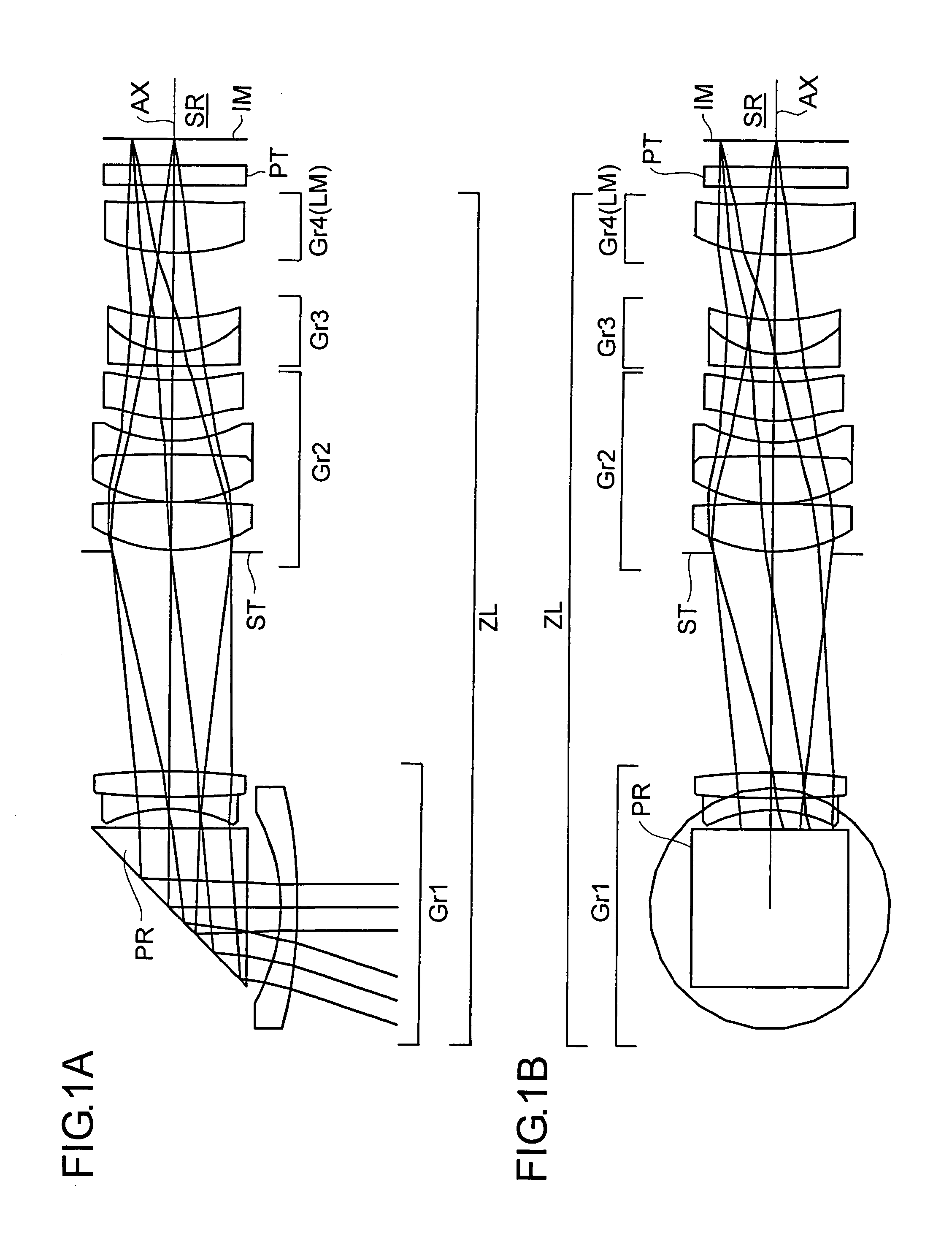
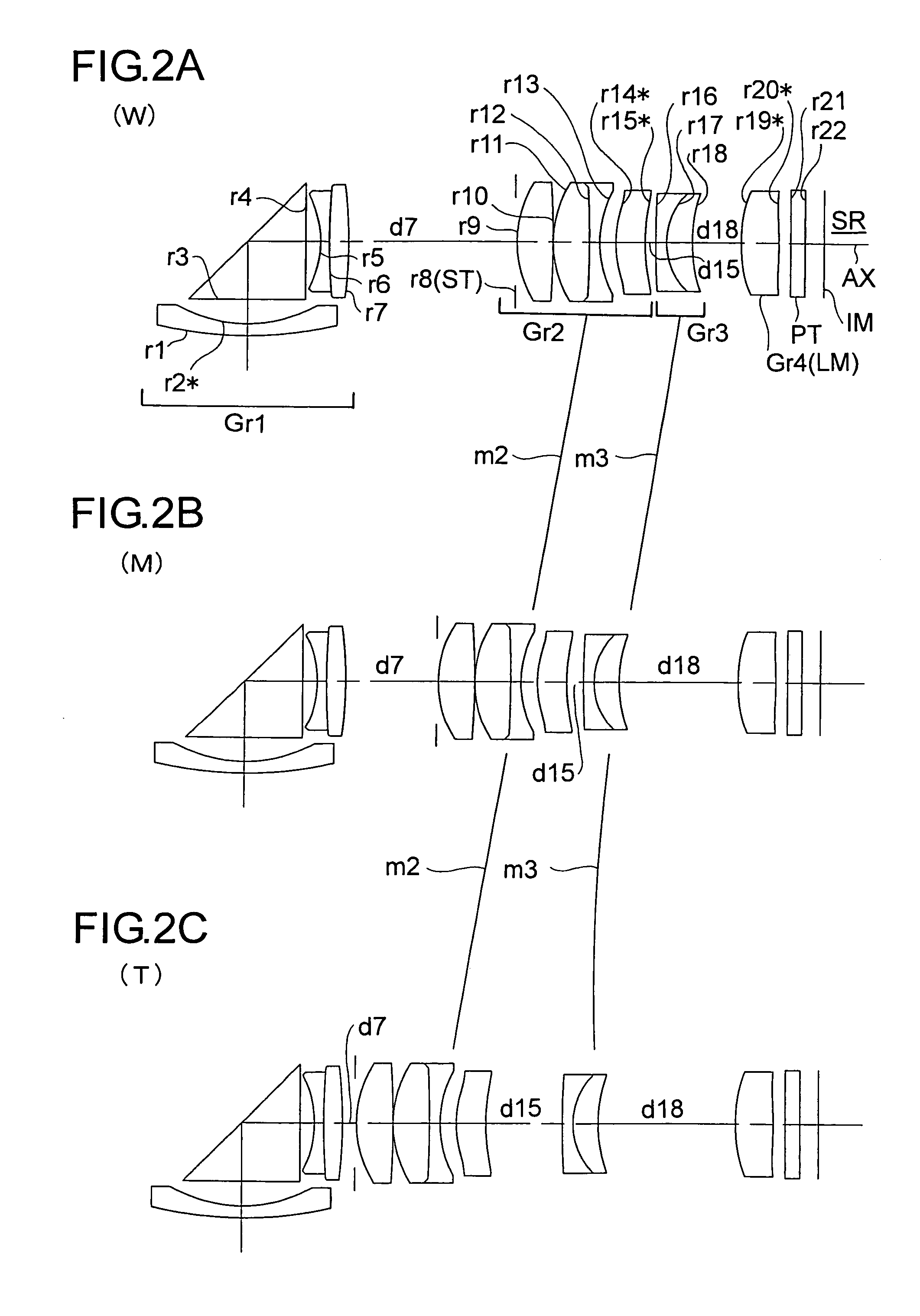
[0067]Hereinafter, practical examples of image-taking lens units embodying the present invention will be presented with reference to their construction data and other data. Examples 1 and 2 presented below are numerical examples corresponding respectively to the first and second embodiments, respectively, described above. Thus, the optical construction diagrams (FIGS. 1A, 1B, 2A, 2B, 2C, and 3; and FIGS. 4A, 4B, 5A, 5B, 5C, 6A, and 6B showing the first and second embodiments also show the lens constructions of Examples 1 and 2, respectively.

[0068]Tables 1 and 2 show the construction data of Example 1, and Tables 3 and 4 show the construction data of Example 2. In the basic optical construction shown in Tables 1and 3 (where i represents the surface number), ri (i=1, 2, 3, . . .) represents the radius of curvature (mm) of the i-th surface counted from the object side; di (i=1, 2, 3, . . .) represents the axial distance (mm) between the i-th and (i+1)th surfaces counted from the object...


PUM


Abstract

An image-taking lens unit has an image-taking lens system that forms an optical image of an object and an image sensor that receives the optical image in a rectangular image-sensing region and converts the optical image into an electrical signal. The image-taking lens system includes a reflective optical element that bends the optical path. Of the lens elements constituting the image-taking lens system, the most image-side lens element called the last lens element is molded of resin, and is given a non-circular outer shape fulfilling a prescribed condition.

Description

[0001]This application is based on Japanese Patent Application No. 2005-169360 filed on Jun. 9, 2005, the contents of which are hereby incorporated by reference.BACKGROUND OF THE INVENTION[0002]1. Field of the Invention[0003]The present invention relates to an image-taking lens unit. More particularly, the present invention relates to an image-taking apparatus, such as a digital camera or a digital appliance equipped with an image capturing capability, that captures an image of a subject with an image sensor, and to a slim, high-zoom-ratio image-taking lens unit suitable for use in such an image-taking apparatus.[0004]2. Description of Related Art[0005]With the recent spread of personal computers, there have been increasing demands for digital cameras, which permit easy capturing of images. With this trend, increasingly slim digital cameras have been sought after, and accordingly increasingly slim image-taking lens systems have been craved for. On the other hand, some digital camera...

Claims


Application Information

Patent Timeline
Patent Type & Authority Patents(United States)
IPC IPC(8): G03B15/00
CPCG02B15/177G02B5/04G02B15/144511
Inventor SOUMA, YOSHIHITOYAMAMOTO, YASUSHIHONDA, TSUTOMU
Owner KONICA MINOLTA PHOTO IMAGING
Why Eureka
Try Eureka