Gas turbine or compressor blade

a compressor blade and gas turbine technology, applied in the direction of liquid fuel engines, marine propulsion, vessel construction, etc., can solve the problems of reducing the life of the blade, and reducing the stress at the junction between the blade aerofoil and the platform, so as to reduce the stress at the upstream end of the notch and distribute it, avoiding the risk of this end cracking

Active Publication Date: 2008-12-02
SN DETUDE & DE CONSTR DE MOTEURS DAVIATION S N E C M A
View PDF2 Cites 10 Cited by
  • Summary
  • Abstract
  • Description
  • Claims
  • Application Information

AI Technical Summary

Benefits of technology

[0010]This notch divides the fairing into two lateral parts, which expand and deform freely relative to each other, thereby reducing the stresses in the joint region between the blade aerofoil and the platform.
[0013]Since they are oriented along the aerodynamic profile of the gas flow over the pressure sides of the blades, they cause little disturbance in the gas flow between the blades and do not create any head loss or turbulence liable to reduce the efficiency of the gas turbine or compressor.
[0015]This hole allows the local stresses at the upstream end of the notch to be reduced and distributed, and avoids the risk of this end cracking.

Problems solved by technology

In operation, the downstream fairings of the blade platforms, which are exposed to high temperatures, expand and deform relative to the aerofoils, thereby creating high stresses at the junctions between the blade aerofoils and the platforms.
These stresses are liable to weaken the blades and reduce their lifetime.

Method used


Image

  • Gas turbine or compressor blade
  • Gas turbine or compressor blade

Examples


Embodiment Construction

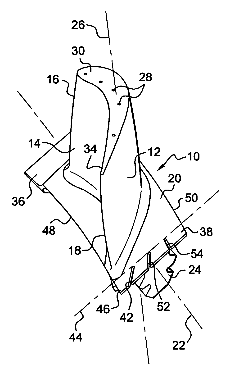
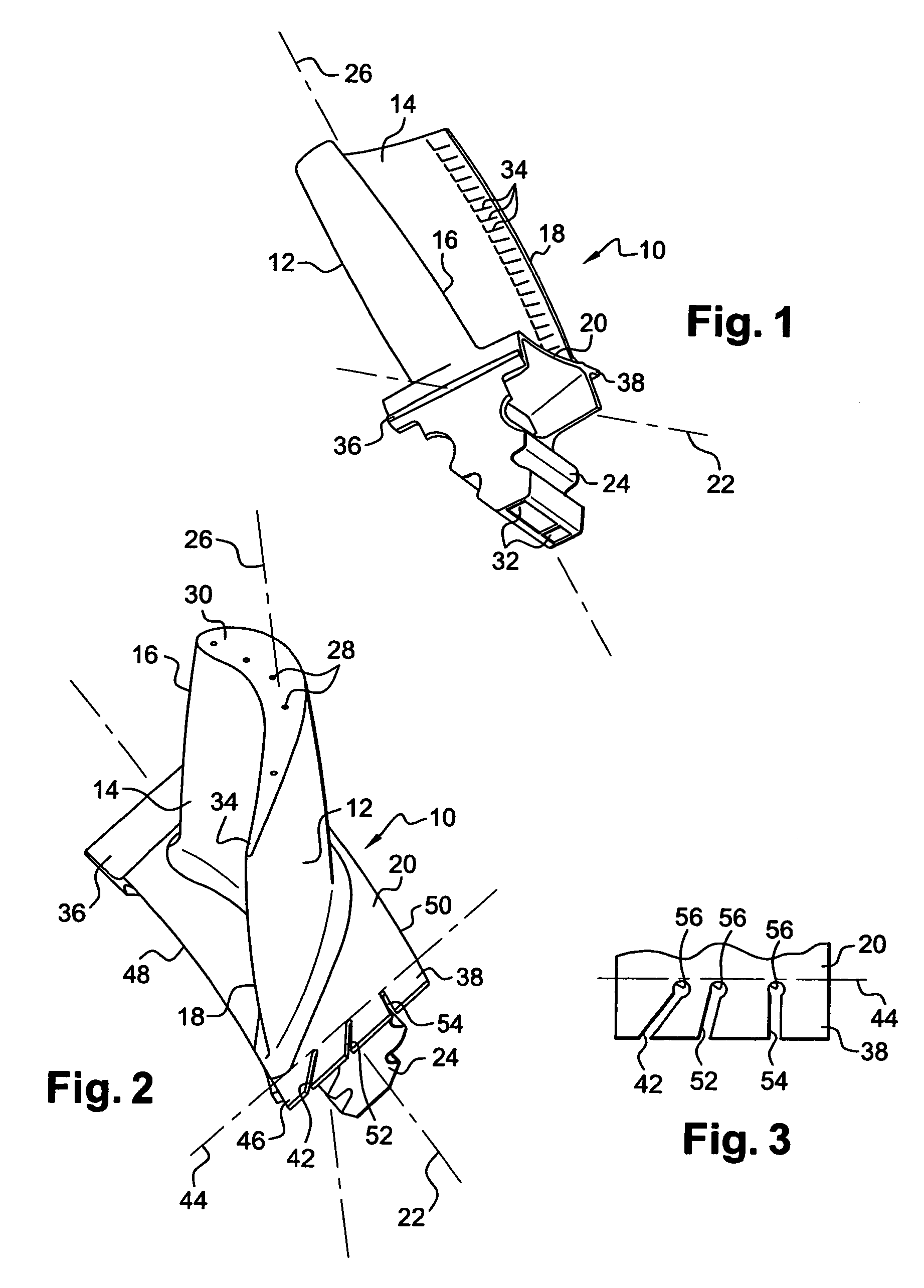
[0023]The blade according to the invention, shown in FIGS. 1 and 2, is a rotor blade of a gas turbine or compressor, in particular of an aircraft turbojet or turboprop engine.

[0024]This blade 10 has a convex outer surface or suction side 12 and a concave inner surface or pressure side 14 that are joined together at their upstream ends by a leading edge 16 and at their downstream ends by a trailing edge 18 for the gases that flow in the gas turbine or compressor.

[0025]The blade 10 furthermore includes a substantially rectangular platform 20 of longitudinal axis 22, which joins the lower end of both the pressure side 14 and the suction side 12 to a root 24, by means of which the blade 10 is mounted on a rotor disc (not shown) of the gas turbine or compressor, by this root 24 being fitted into a cavity of corresponding shape on the periphery of the rotor disc.

[0026]Thanks to this male / female fitting, which is of the fir-tree type in the example shown, the blade 10 is retained radially ...


PUM


Abstract

A gas turbine or compressor blade, includes a convex outer surface or suction side and a concave inner surface or pressure side, these sides being joined at their upstream ends by a leading edge and at their downstream ends by a trailing edge for the gases and terminating on a platform, one part of which includes a downstream fairing that includes at least one through-notch that extends substantially between a transverse line passing through the trailing edge and the downstream end of the fairing.

Description

[0001]The present invention relates to a rotor or stator blade for a gas turbine or compressor, and to a turbojet turbine or compressor comprising a plurality of these blades.BACKGROUND OF THE INVENTION[0002]A gas turbine or compressor blade comprises an aerofoil, defined by a convex outer surface or suction side and a concave inner surface or pressure side, these being joined together at their upstream ends by a leading edge and at their downstream ends by a trailing edge for the gases. The pressure side and the suction side terminate on a platform which may be provided with a blade root of the dovetail or fir-tree type intended to be inserted into a corresponding slot in a rotor disc of the gas turbine or compressor, when this is a rotor blade or moving blade.[0003]In general, the platform has a fairing that extends towards the upstream end from the leading edge and a fairing that extends towards the downstream end from the trailing edge. The upstream and downstream fairings of th...

Claims


Application Information

Patent Timeline
Patent Type & Authority Patents(United States)
IPC IPC(8): F01D11/00F01D5/14
CPCF01D5/147F05D2260/94F05D2260/941Y02T50/673F05D2240/80Y02T50/60
Inventor BIL, ERIC STEPHENHERVY, NICOLASSCHLESINGER, THOMAS
Owner SN DETUDE & DE CONSTR DE MOTEURS DAVIATION S N E C M A
Why Eureka
Try Eureka