Apparatus and method for detecting displacement of a movable member of an electronic musical instrument

a technology of electronic musical instruments and actuators, applied in the field of electronic musical instruments, can solve the problems of inability to accurately detect the amount of pedal stepping, and the deformation of rubber sensors in the shape of each method, and achieve the effect of superior mechanical durability and good efficiency

Active Publication Date: 2008-12-02
ROLAND CORP
View PDF12 Cites 15 Cited by
  • Summary
  • Abstract
  • Description
  • Claims
  • Application Information

AI Technical Summary

Benefits of technology

[0011]Therefore, it is an advantage of embodiments of the present invention to provide an apparatus and method for providing a displacement sensor that has superior mechanical durability and that can withstand use over a long period of time.
[0012]An embodiment of the present invention that achieves the object described above is characterized in that the displacement sensor is furnished with a sensor structure, such as a sensor sheet, for which the resistance value changes in conformance with the area that has been pressed and a coil spring that has a conical shape. The wider end of said conical shape is in contact with the previously mentioned sensor sheet and increases the area of pressing of said sensor sheet in proportion to the compression of the spring.
[0013]The coil spring with which an embodiment of the present invention is furnished possesses durability with respect to the compression force that is received from the object that is displaced. In addition, since the displacement sensor is furnished with a structure in which the mechanical rubbing portion that is the cause of abrasion is excluded, the mechanical durability is superior and long-term use is possible.
[0016]As has been explained above, an embodiment of the present invention is superior in mechanical durability compared to the displacement sensors of the past and can withstand use for a long period of time.

Problems solved by technology

However, in those cases where the displacement of a pedal is detected, the displacement sensor is required to have the durability to withstand the force that is repeatedly applied from the pedal over a long period of time.
Each of the methods mentioned above has problems such as those described below.
In Method 1, when the rubber sensor is used over a long period of time and its shape is repeatedly changed in conformance with the stepping operation of the pedal, the rubber sensor becomes deformed in shape such that it becomes impossible to accurately detect the amount that the pedal has been stepped on.
In Method 2, when the volume control is used for a long period of time, the mechanical sliding portion is abraded and that becomes a problem.

Method used


Image

  • Apparatus and method for detecting displacement of a movable member of an electronic musical instrument
  • Apparatus and method for detecting displacement of a movable member of an electronic musical instrument
  • Apparatus and method for detecting displacement of a movable member of an electronic musical instrument

Examples


Embodiment Construction

[0026]In the following description of preferred embodiments, reference is made to the accompanying drawings which form a part hereof, and in which is shown by way of illustration specific embodiments in which the invention may be practiced. It is to be understood that other embodiments may be utilized and structural changes may be made without departing from the scope of the preferred embodiments of the present invention.

[0027]An explanation will be given below regarding preferred embodiments of the present invention while referring to the drawings.

[0028]First, an explanation will be given regarding a first preferred embodiment of the present invention.

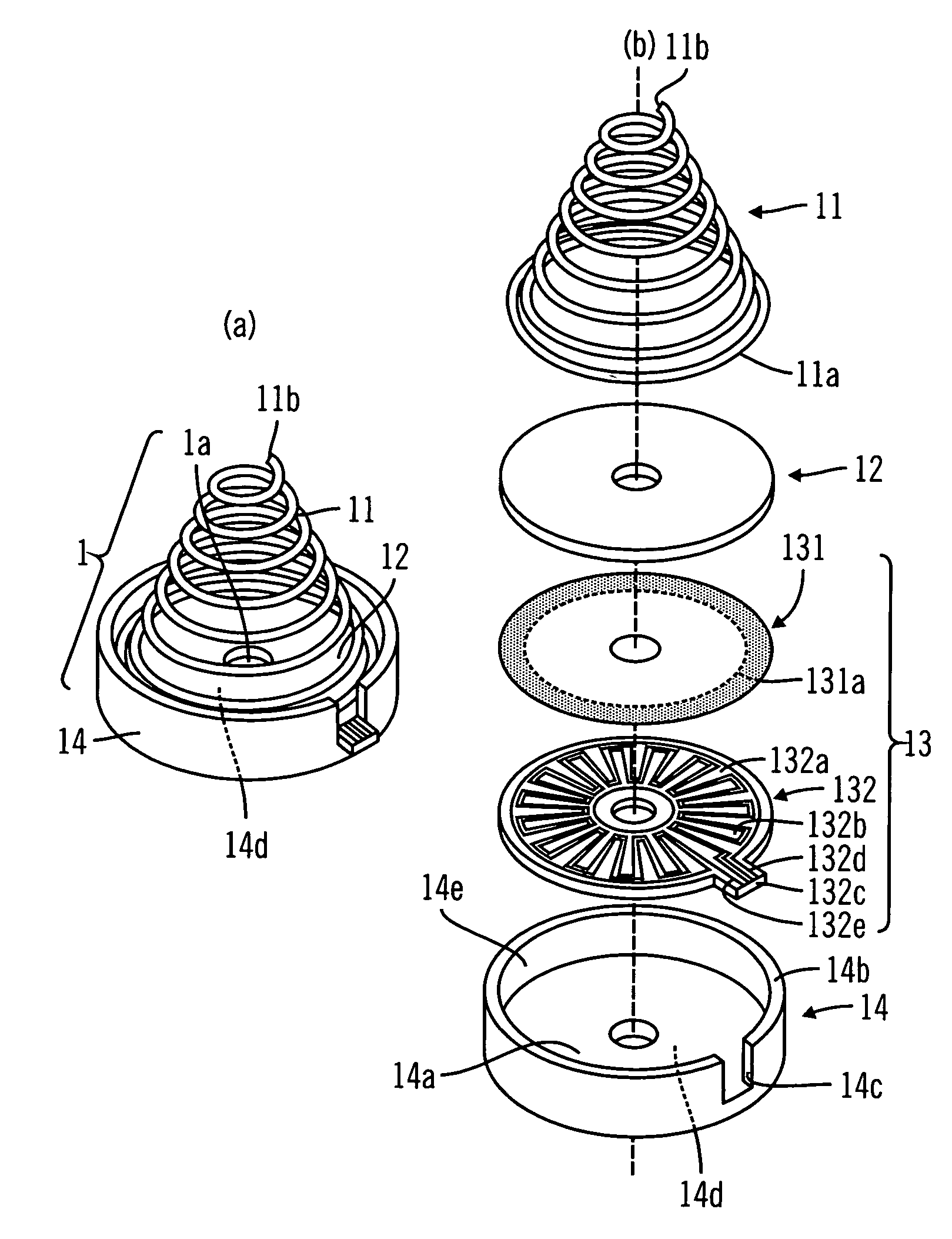
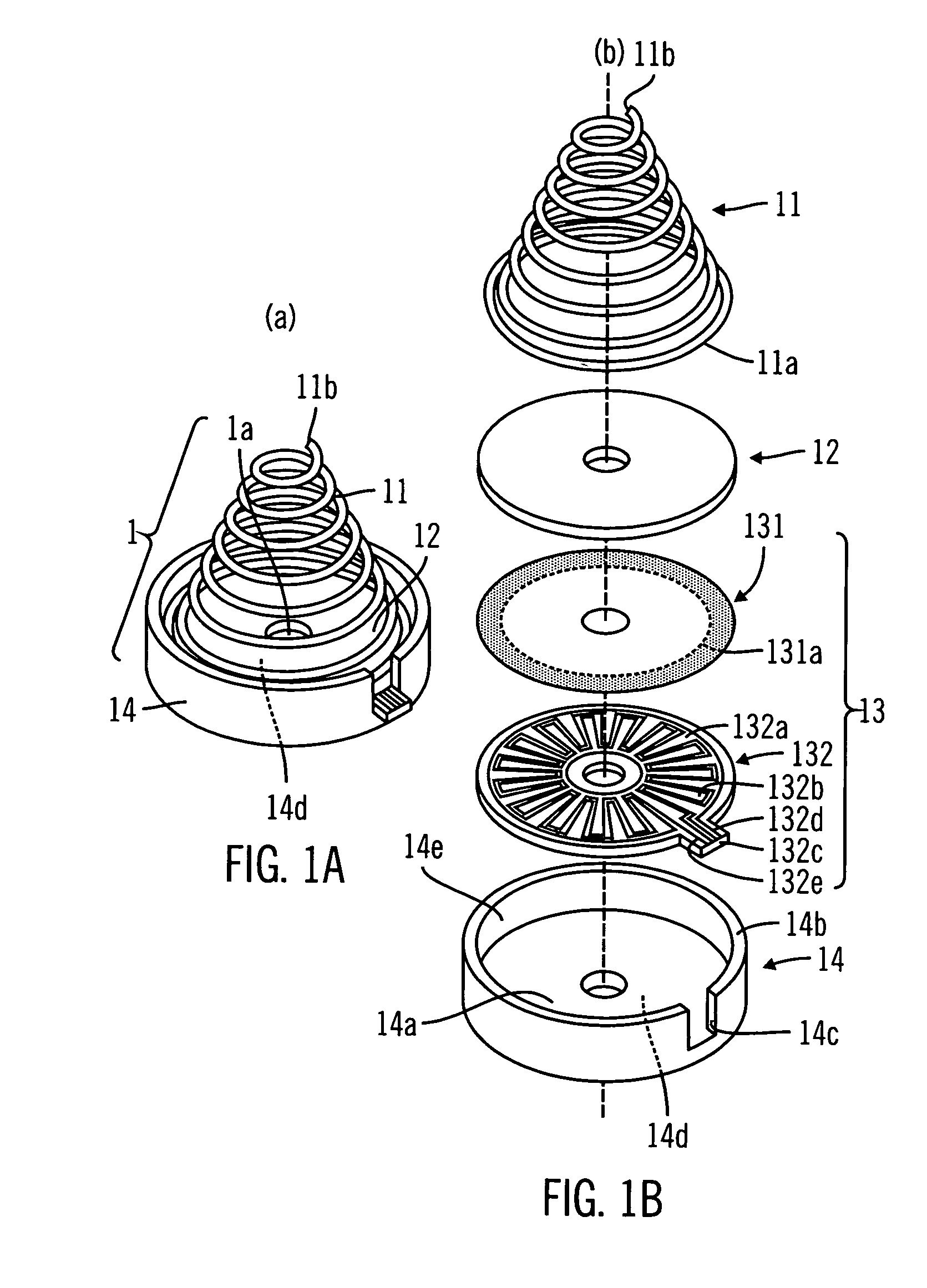
[0029]FIGS. 1(a) and 1(b) are oblique view drawings that show a first preferred embodiment of the displacement sensor of the present invention.

[0030]FIG. 1(a) is an exterior oblique view drawing seen from diagonally above the displacement sensor 1 and FIG. 1(b) is a disassembled oblique view drawing of the displacement sensor.

[0031]Th...


PUM


Abstract

An apparatus for detecting the displacement of a movable member of an electronic musical instrument. The apparatus has superior mechanical durability compared to displacement sensors of the past and can withstand long-term use. The apparatus includes a sensor that provides a detectable electrical characteristic having a value and a spring that, when compressed upon displacement of the movable member acts with the sensor, causing the value of the electrical characteristic to change. The value of the electrical characteristic represents the amount of displacement of the movable member and is used by a controller of the electronic musical instrument.

Description

BACKGROUND OF THE INVENTION[0001]1. Field of the Invention[0002]The present invention relates, generally, to electronic musical instruments and, in preferred embodiments, to electronic musical instruments having the capability of detecting the amount of displacement of a pedal or of other movable members.[0003]2. Description of Related Art[0004]In electronic musical instruments, displacement sensors are used as sensors to detect the amount of displacement of, for example, a pedal.[0005]Examples of prior methods for the detection of the amount of displacement are described below.[0006]Method 1: This is a method in which, for example, a displacement sensor is configured with a rubber sensor that changes shape in conformance with the amount that a pedal is stepped on and a sensor sheet that is pressed by the rubber sensor as the rubber sensor changes shape. The resistance value of the sensor sheet changes in conformance with the area of the sheet that is pressed.[0007]Method 2: This is...

Claims


Application Information

Patent Timeline
Patent Type & Authority Patents(United States)
IPC IPC(8): G10H3/00
CPCG10H1/34G10H2220/561G10H2230/331
Inventor YOSHINO, KIYOSHIARAI, KAZUHIRO
Owner ROLAND CORP
Why Eureka
Try Eureka