Image processing device

a technology of image processing and supporting members, which is applied in the direction of electrographic process apparatus, instruments, printing, etc., can solve the problems of deformation of the supporting member, and deformation of the body, so as to achieve stable installation conditions, high accuracy, and high accuracy

Active Publication Date: 2008-12-02
KYOCERA DOCUMENT SOLUTIONS INC
View PDF5 Cites 2 Cited by
  • Summary
  • Abstract
  • Description
  • Claims
  • Application Information

AI Technical Summary

Benefits of technology

[0012]Also, since the optical unit is supported in three points that form a triangle in the same direction as the rough triangle formed by the legs when viewed from underneath, the optical unit is necessarily supported in three points that are as close as possible to the three points of the legs when viewed from underneath. In other words, the three points supporting the optical unit can be closer to the three points of the legs when the size of the optical unit is as large as possible when viewed from underneath (close to the size of the undersurface of the apparatus). Therefore, the optical instruments mounted in the optical unit can be positioned with high accuracy, hardly influenced from the warp of the structure of the apparatus body.
[0013]Particularly, the positions overlapping with each of the legs in three points or the three points in the vicinity of these legs when viewed from underneath, are the position hardly influenced from the warp caused by its own weight of the apparatus body, and therefore, when the optical unit has a structure supported in such three points, the optical instruments mounted in such optical unit are hardly influenced from the warp of the apparatus body, thereby being positioned with high accuracy.
[0016]In the sheet delivery path in the nearly vertical direction, such as a delivery roller including such as a guide for guiding sheet and a fixing roller, as well as its drive mechanism are arranged in plurality in the longitudinal direction, thereby generally applying a large load intensively on its lower part. Thus, when the two points among the three points, which are provided with the legs, are placed in the lower part of the sheet delivery path in the nearly vertical direction, the image processing apparatus can obtain a stable installation condition, and therefore, the warp of the apparatus body caused by its own weight can be limited as much as possible.
[0018]In addition, since the optical unit is supported by the structure of the apparatus body in three points that form a triangle in the same direction as the rough triangle formed by the legs in three points when viewed from underneath, the optical instruments mounted in the optical unit can be positioned with high accuracy, hardly influenced from the warp of the structure of the apparatus body. Particularly, the positions overlapping with each of the legs in three points, or the three points in the vicinity of these legs when viewed from underneath, are the position hardly influenced from the warp caused by its own weight of the apparatus body, and therefore, when the optical unit is supported in such three points, the optical instruments can be positioned with high accuracy, hardly influenced from the warp of the apparatus body.
[0019]Moreover, when the two points among the three points where the legs are provided, are placed in the lower part of the sheet delivery path in the nearly vertical direction where intensively bears a large load, the image processing apparatus can obtain a stable installation condition, and therefore, the warp of the apparatus body caused by its own weight can be limited as much as possible.

Problems solved by technology

However, as described in Japanese Unexamined Patent Publication No. 2002-187308, even if the optical instruments are unitized, when the supporting member in the side of the apparatus body (the frame of the body side) for supporting the optical unit is warped by such as differences of elevation (distribution of unevenness) on the installation surface of the apparatus, there still remains a problem that the accuracy of positioning of the optical instruments is degraded.
In addition, as described in Japanese Unexamined Patent Publication No. 2001-117302, even when legs are provided in three points on the undersurface of the apparatus body in a manner so as to form a rough triangle, the supporting member (frame) in the side of the apparatus body may warped because of its own weight, and in if so, there occurs a problem that the accuracy of positioning of the optical instruments may be degraded by the warp of said supporting members, depending on the supporting structure of the optical unit.

Method used


Image

  • Image processing device
  • Image processing device
  • Image processing device

Examples


Embodiment Construction

[0026]With embodiments of the present invention described hereinafter with reference to the accompanying drawings, it is to be understood that the invention is not limited to those precise embodiments, and that various changes and modifications may be effected therein by one skilled in the art without departing from the scope or spirit of the invention as defined in the appended claims.

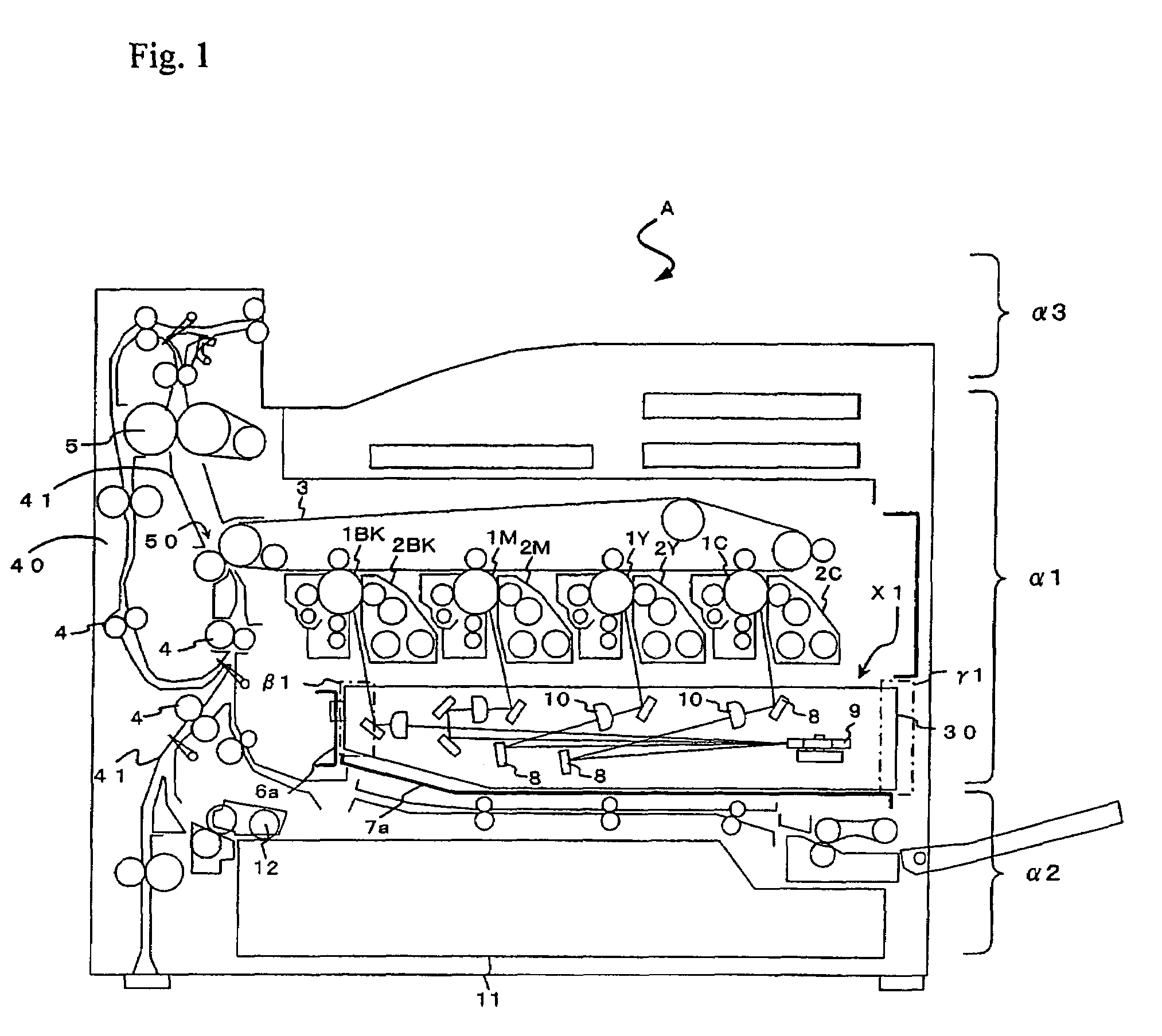
[0027]Firstly, with reference to the cross-sectional view illustrated in FIG. 1, the general structure of entire Image processing apparatus A according to the present invention is described. Image processing apparatus A illustrated in FIG. 1 is a printer (color printer) as one example of the image processing apparatus of electrophotographic system, however, this invention can also be applied to other image processing apparatuses, such as copy machines and facsimiles.

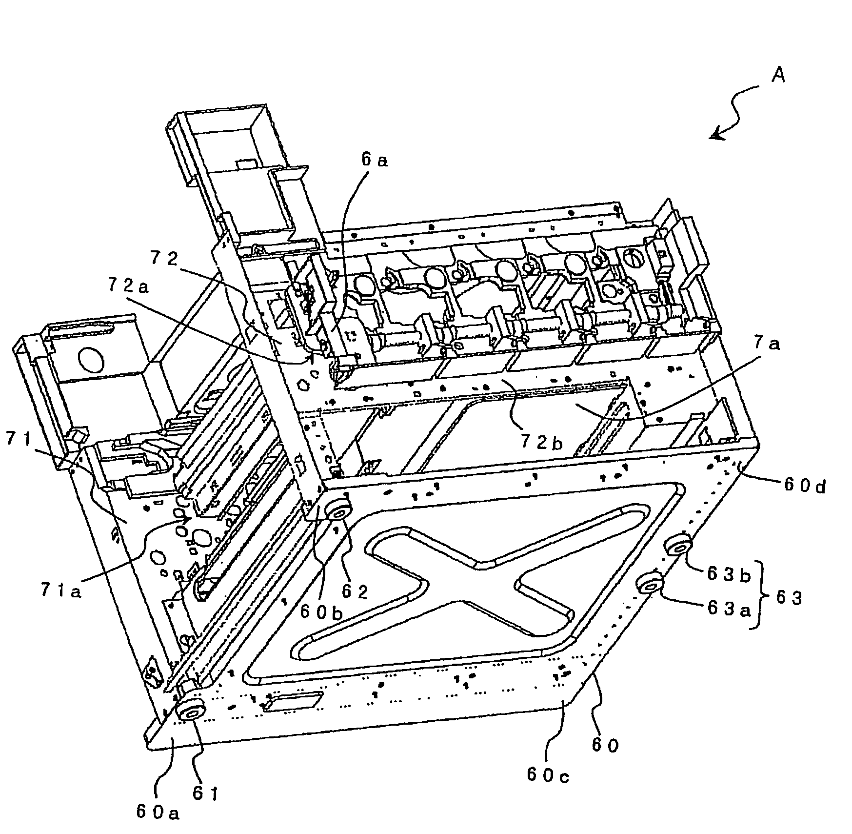
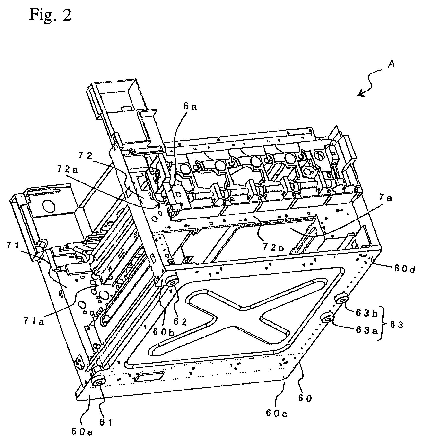
[0028]As shown in FIG. 1, Image processing apparatus A comprises Optical unit X1, unitized by a chassis 30 made from a single casting by ...


PUM


Abstract

An image processing apparatus having a structure in which the positioning accuracy of the optical instruments related to image processing are hardly influenced from the condition of the installation surface of the apparatus body. Near the edges of floor plate 60 forming the undersurface of the body of image processing apparatus A, four legs 61, 62, 63a, and 63b are provided in a protruding manner in three points forming generally a triangle, and optical unit X1 in which the optical instruments are mounted is supported by vertical positioning plate 6a or horizontal positioning plate 6a, which are a part of the apparatus body's structure, in three points forming a triangle in the same direction as the triangle formed by Legs 61, 62, and 63 in three points when viewed from underneath, and then, these three points are arranged in the position near each of the three points provided with legs 61, 62, and 63 when viewed from underneath.

Description

BACKGROUND OF THE INVENTION[0001]1. Field of the Invention[0002]The present invention relates to an image processing apparatus comprising an optical unit in which an optical instrument related to image processing is mounted.[0003]2. Description of the Related Art[0004]Image processing apparatuses, such as copy machines, printers, and facsimiles are housing the optical instruments for image processing in their body chassis.[0005]Also, as have been described in the prior art 1 (Japanese Unexamined Patent Publication No. 2002-187308), with respect to the image processing apparatuses in these days, the optical instruments relevant to image processing, such as the light source (such as, razor beam outputting apparatus) for performing beam light output for writing an electrostatic latent image onto, for example, an image supporter (for a typical example, photoreceptor drum), one or a plurality of deflecting mirrors for guiding beam light to the photoreceptor drum, the fθ lens for performi...

Claims


Application Information

Patent Timeline
Patent Type & Authority Patents(United States)
IPC IPC(8): B41J29/06
CPCG03G15/04G03G21/1666G03G21/1647G03G2221/1636G03G15/0435
Inventor MASAKI, AKIHIROMIYAMOTO, TERUYUKIHATAKEYAMA, CHISATO
Owner KYOCERA DOCUMENT SOLUTIONS INC
Why Eureka
Try Eureka