Outboard engine unit

a technology for engine units and intake manifolds, which is applied in the direction of machines/engines, combustion air/fuel air treatment, and feed systems, etc., can solve the problems of inability to adopt an engine cover, inability to achieve sufficient output, and inability to minimize the protrusion in the width direction of the highest intake tube at the top of the intake manifold. , to achieve the effect of increasing the distance, reducing the height, and reducing the length of the protrusion

Inactive Publication Date: 2008-12-09
HONDA MOTOR CO LTD
View PDF2 Cites 0 Cited by
  • Summary
  • Abstract
  • Description
  • Claims
  • Application Information

AI Technical Summary

Benefits of technology

[0011]In the outboard engine unit, channels in the intake tubes connected to the surge tank are given a transversely flat cross-sectional shape that is a shorter in the crosswise dimension than in the vertical dimension. The space between the openings of the vertically adjacent intake tubes can therefore be increased, the intake flow of one adjacent opening is less liable to flow to another opening, and mutual interference between adjacent openings of the intake tubes can be prevented. For this reason, the intake pulses of the surge tank can be more effectively used and engine output can be improved. The dimension in the height of the intake tubes can be reduced, the outside dimensions of the outboard engine unit can be made more compact, and sufficient space inside the engine compartment of the outboard engine unit can be more efficiently assured.
[0013]Therefore, the vertically arranged intake tubes have essentially the same cross-sectional area, and the highest intake tube is long in the longitudinal direction. Therefore, the length of the protrusion in the width direction of the highest intake tube at the top of the intake manifold can be minimized. Since the lowest intake tube is long in the transverse direction, the height can be reduced while increasing the distance in the width direction, and the dimension in the height direction of the intake manifold can be reduced while increasing the cross-sectional area of the intake tubes. Therefore, the intake tubes can be effectively disposed along the inner wall of the engine cover in which the top portion is narrow and the lower portion is wide.
[0014]It is preferable that each of the intake tubes is provided with an outer long channel portion and a short channel portion near the engine that are arranged in parallel inside the engine compartment, the channel portions merge in a shared channel on a downstream side, the cross-sectional shape of the highest long channel portion selected from the long channel portions is long in the longitudinal direction, and the lowest long channel portion has a cross-sectional shape long in the transverse direction, and each of the short channel portions is provided with an on / off valve that operates simultaneously in the same direction. Thus, the on / off valves disposed in the short intake channels are opened and closed to thereby switch the intake channels from high speed and high load operation to low speed and low load operation in a simple manner.
[0015]It is also preferable that the cross-sectional shape of channels in the intake tubes is one in which the highest long channel portion and a shared channel in communication therewith are long in the longitudinal direction, and the lowest long channel portion and the shared channel in communication therewith are long in the transverse direction, and the short channel portions have essentially the same cross-sectional shape. Therefore, the cross-sectional area of the intake tubes including the shared channel can be increased, higher output can be assured, and the on-off valves that open and close the inner short channel portions can be reliably operated.

Problems solved by technology

When the cross-sectional area of the tubes is increased to achieve higher engine output, the spacing between the openings to the cylinders becomes narrow, and sufficient output cannot be achieved because of intake interference when the ignition sequence begins from the intake tube in the highest position and ends with the intake tube in the lowest position.
It is therefore impossible to adopt an engine cover in which the upper portion of the cover is made narrow and the cover gradually becomes wider in the downward direction, and other problems are encountered.

Method used


Image

  • Outboard engine unit
  • Outboard engine unit
  • Outboard engine unit

Examples


second embodiment

[0066]The intake manifold 50 is disposed on the left side surface of the engine 2, as shown in FIGS. 10, 11; and 12. The intake manifold 50 is composed of a large-capacity surge tank 51 that faces the intake silencer 7 (FIG. 12), and an intake tube portion 52 connected so as to be in communication with the downstream portion of the surge tank 51.

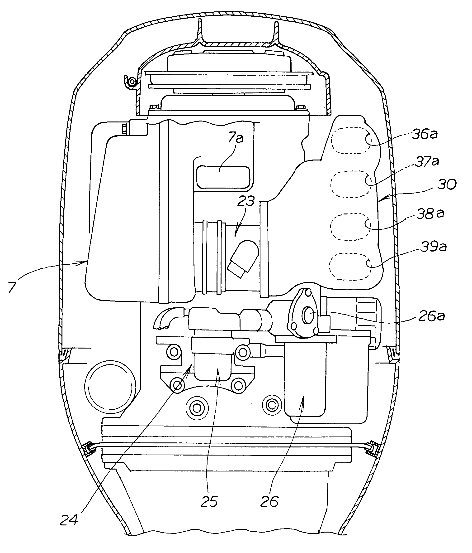
[0067]In this embodiment, the intake tube portion 52 is composed of four intake tubes 61, 62, 63, and 64 because the engine 2 has four cylinders aligned in the vertical direction. The intake tubes 61 to 64 are in communication with the surge tank 51.

[0068]The four intake tubes 61, 62, 63, and 64 branch off from the downstream portion 5la of the surge tank 51, and are composed of base end portions 52a that are in communication with the surge tank 51. The furthest downstream portions 52b of the intake tube portion 52 are connected to the intake ports of the cylinder head 4 as the downstream end portions of the intake tubes 61 to 64, respectiv...

third embodiment

[0106]The cross-sectional shapes of the intake tubes 361 to 364 shown in FIG. 18 are designed so that the surfaces on the engine side are uniformly perpendicular as shown in the diagrams, and the upper portion of the outer surfaces 361a to 363a is narrow and the lower portion is wide, as described above. In other words, the intake tubes 361 to 364 arranged in the vertical direction slope so as to protrude outward from the higher positions to the lower positions, and the intake tubes 361 to 364 are designed to have the same cross-sectional areas. Therefore, the width direction of the highest first intake tube 361 can be effectively reduced.

[0107]The width direction of the lowest fourth intake tube 364 is increased, as is the dimension in the longitudinal direction of the intake manifold. Therefore, the intake manifold can be made to effectively follow the inner wall of the engine cover in which the upper portion is narrow and the lower portion is wide.

[0108]In the intake tubes accor...


PUM


Abstract

An outboard engine unit has an intake manifold extending in a front-and-rear direction along one side of an engine block and comprised of a surge tank and a plurality of intake tubes communicating with the surge tank. Each of the intake tubes is arranged so as to be separated in a vertical direction. The shape of the channel cross section of each of the intake tubes is a flat shape in which the dimension in the vertical direction is less than the dimension in a crosswise direction.

Description

FIELD OF THE INVENTION[0001]The present invention relates to an improved outboard engine unit and, in particular, to an intake manifold of an engine.BACKGROUND OF THE INVENTION[0002]A conventional intake manifold for preventing a reduction in engine output in an engine provided with a plurality of intake tubes that extend at different slope angles from a surge tank is disclosed in JP 10-184469 A.[0003]The manifold disclosed in JP 10-184469 A has a single surge tank and four vertically arranged intake tubes that are in communication with the surge tank. With an intake manifold disposed on one side of the engine, the slope angles of the intake tubes connected to the four combustion chambers formed in the cylinder head are different. Therefore, to prevent the length of the intake tubes from being nonuniform, the intake tube having the lowest slope angle is disposed so as to extend most greatly to the side, and the intake tube having the highest slope angle is disposed so as to extend b...

Claims


Application Information

Patent Timeline
Patent Type & Authority Patents(United States)
IPC IPC(8): F02M35/10
CPCF02M35/10052F02M35/10072F02M35/10124F02M35/112F02M35/167F02M35/1036
Inventor TSUBOUCHI, MASANORIISHIZAKA, KAZUHIRO
Owner HONDA MOTOR CO LTD
Why Eureka
Try Eureka