Supercharge Your Innovation With Domain-Expert AI Agents!

Mold core having a temperature control apparatus

a technology of temperature control apparatus and mold core, which is applied in the direction of manufacturing tools, semiconductor/solid-state device details, food shaping, etc., can solve the problems of slow temperature reaching of water circulation cooling system and occupying a lot of spa

Inactive Publication Date: 2008-12-09
HON HAI PRECISION IND CO LTD
View PDF5 Cites 4 Cited by
  • Summary
  • Abstract
  • Description
  • Claims
  • Application Information

AI Technical Summary

Benefits of technology

Enables timely and precise temperature control of the mold core during the molding process, ensuring accurate micro-lens array formation while occupying less space compared to traditional systems.

Problems solved by technology

However, the water circulation cooling system is slow to reach a predetermined temperature when the molding temperature changes.
Furthermore, the water circulation cooling system can take up a lot of space.

Method used


Image

  • Mold core having a temperature control apparatus
  • Mold core having a temperature control apparatus
  • Mold core having a temperature control apparatus

Examples


Embodiment Construction

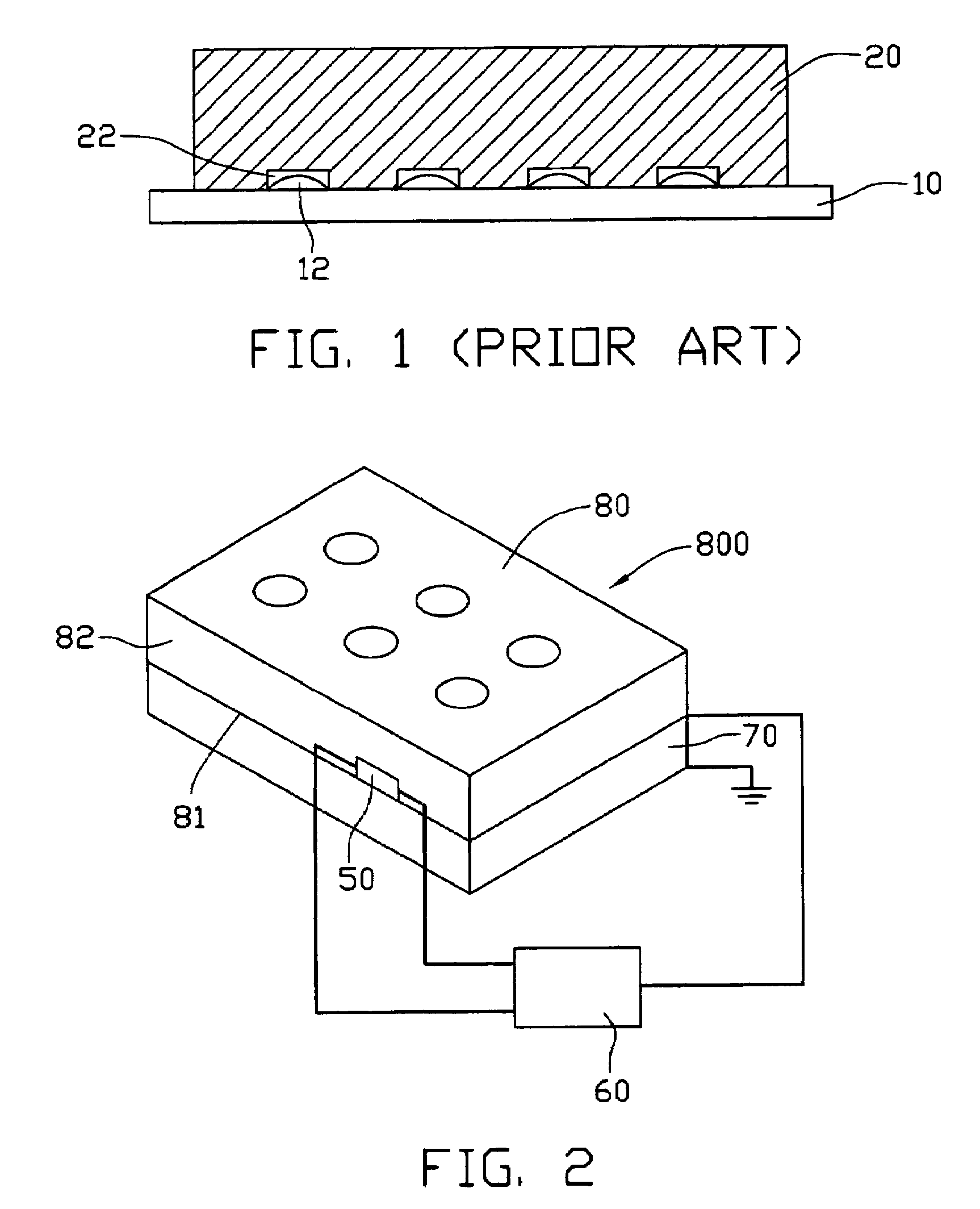
[0012]Referring to FIG. 2, in a preferred embodiment, a temperature controlling apparatus is used to control temperature of a predetermined target such as a mold core 800 during a press molding process. In this embodiment, the mold core 800 has a cuboid shape, including a forming surface 80, an opposite non-forming surface 81, and four side surfaces 82. It is to be understood that the mold core 800 can also have a different shape, and have different surfaces.

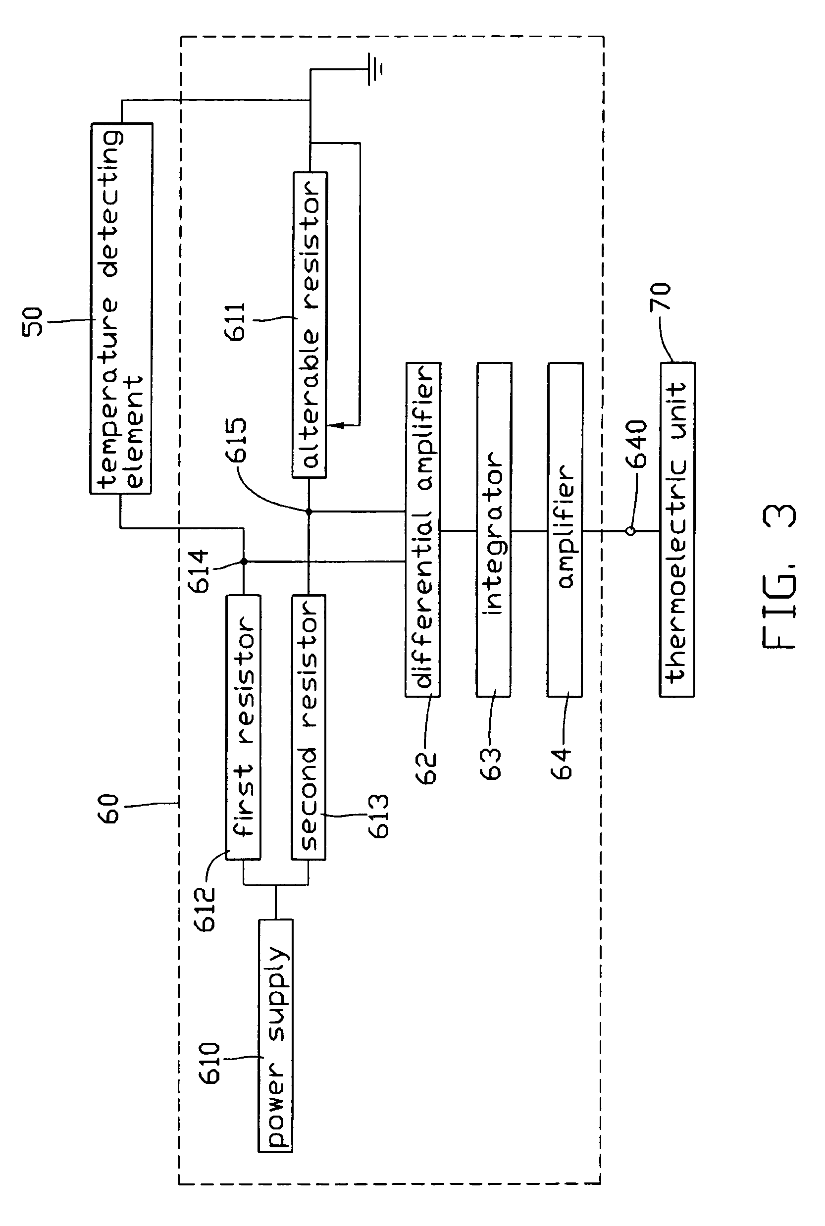
[0013]The temperature control apparatus includes a temperature detecting element 50 such as a thermistor, a control circuit 60, and a thermoelectric unit 70. The temperature detecting element 50 is attached to the side surface 82 of the mold core 800 for detecting the temperature of the mold core 800. The control circuit 60 is electrically connected to the temperature detecting element 50, and the thermoelectric unit 70 is electrically connected to the control circuit 50. The thermoelectric unit 70 contacts the non-forming surfa...


PUM

PropertyMeasurementUnit
temperatureaaaaaaaaaa
transparentaaaaaaaaaa
pressureaaaaaaaaaa

Abstract

An temperature control apparatus includes a temperature detecting element (50), a control circuit (60), and a thermoelectric unit (70). The temperature detecting element contacts to a first surface (82) of a predetermined target (800). The control circuit is electrically connected to the temperature detecting element. The thermoelectric unit is electrically connected to the control circuit, and contacts a second surface of the predetermined target. The temperature detecting element detects a temperature signal. The temperature signal is input into the control circuit. The control circuit changes the temperature signal into an electrical current signal, and the electrical current signal drives the thermoelectric unit to control the temperature of the predetermined target.

Description

TECHNICAL FIELD[0001]The present invention generally relates to apparatuses for temperature control, more particularly, to an electric apparatus for controlling the temperature in micro-lens arrays.BACKGROUND[0002]Usually, micro-lens arrays are used in net-like distributed light guide plates for equably guiding light. The micro-lens array has a plurality of hemispherical lenses. The micro-lens array is ususally made of a transparent material such as polycarbonate or polymethyl methacrylate (PMMA) by heat press molding. Before molding the micro-lens array, a mold core having a plurality of tiny grooves is made using electroforming micro molding lithography. A transparent base is then pressed by the mold core under high temperature and high pressure in a manner so as to create a net-like micro-lens array. The hemispherical lenses are formed by the cohesion and surface tension of the base material under high temperature and high pressure. Thus, the hemispherical lenses may not have the...

Claims


Application Information

Patent Timeline
Patent Type & Authority Patents(United States)
IPC IPC(8): B29C45/72H10N10/10
CPCB29C43/021B29C43/52B29C43/58H01L23/34H01L23/38B29C33/08B29C2043/5816B29L2011/0016H01L2924/0002H01L2924/00
Inventor LIN, JHY-CHAIN
Owner HON HAI PRECISION IND CO LTD
Features
  • R&D
  • Intellectual Property
  • Life Sciences
  • Materials
  • Tech Scout
  • Unparalleled Data Quality
  • Higher Quality Content
  • 60% Fewer Hallucinations
Learn More