Sterilizing lamp

a sterilizing lamp and lamp body technology, applied in the field of uvc sterilizing lamps, can solve the problems of uv-c sterilization, sensitive to water spray and water jets,

Inactive Publication Date: 2008-12-09
BARO GMBH & CO KG
View PDF46 Cites 19 Cited by
  • Summary
  • Abstract
  • Description
  • Claims
  • Application Information

AI Technical Summary

Benefits of technology

[0008]The provision of a flexible protective cover guarantees that in the event the emitter foundation breaks, no splinters can get unnoticed onto the treatment goods arranged underneath of the UV-C sterilizing lamp, or into the cycle of sterilizing systems and contaminate these, but remain inside the protective cover. Furthermore, the provision of the protective cover also achieves a protection against water spray and water jets, so that the UV-C sterilizing lamps may be cleaned in the traditional way in case of dirt accumulation, and that even the requirements for a rating in the IP65 system of protection are met, which means at the same time an expansion of the potential field of application of the UV-C sterilizing lamps of the invention.
[0010]An embodiment of the present invention provides that the UV-C emitter is cast into the base in the area of its electrical connections by means of casting material, and thereby the base is sealed off to the environment. Here, the casting material should be resistant to UV-C radiation. The base and the UV-C emitter form a unit by means of the casting material, so that the electric elements inside of the base are protected against the penetration of humidity, and furthermore an exchange of a possibly defective UV-C emitter, for example by untrained personnel, may be effectively prevented.

Problems solved by technology

A disadvantage of the known UV-C sterilizing lamps is on the one hand, that they are sensitive to water spray and water jets.
On the other hand, the emitter foundation of such a UV-C sterilizing lamp may break, so that the falling splinters of the UV-C sterilizing lamp contaminate the treated goods, or get into the cycle of air sterilizing systems, without this being noticed.

Method used


Image

  • Sterilizing lamp
  • Sterilizing lamp
  • Sterilizing lamp

Examples


Embodiment Construction

)

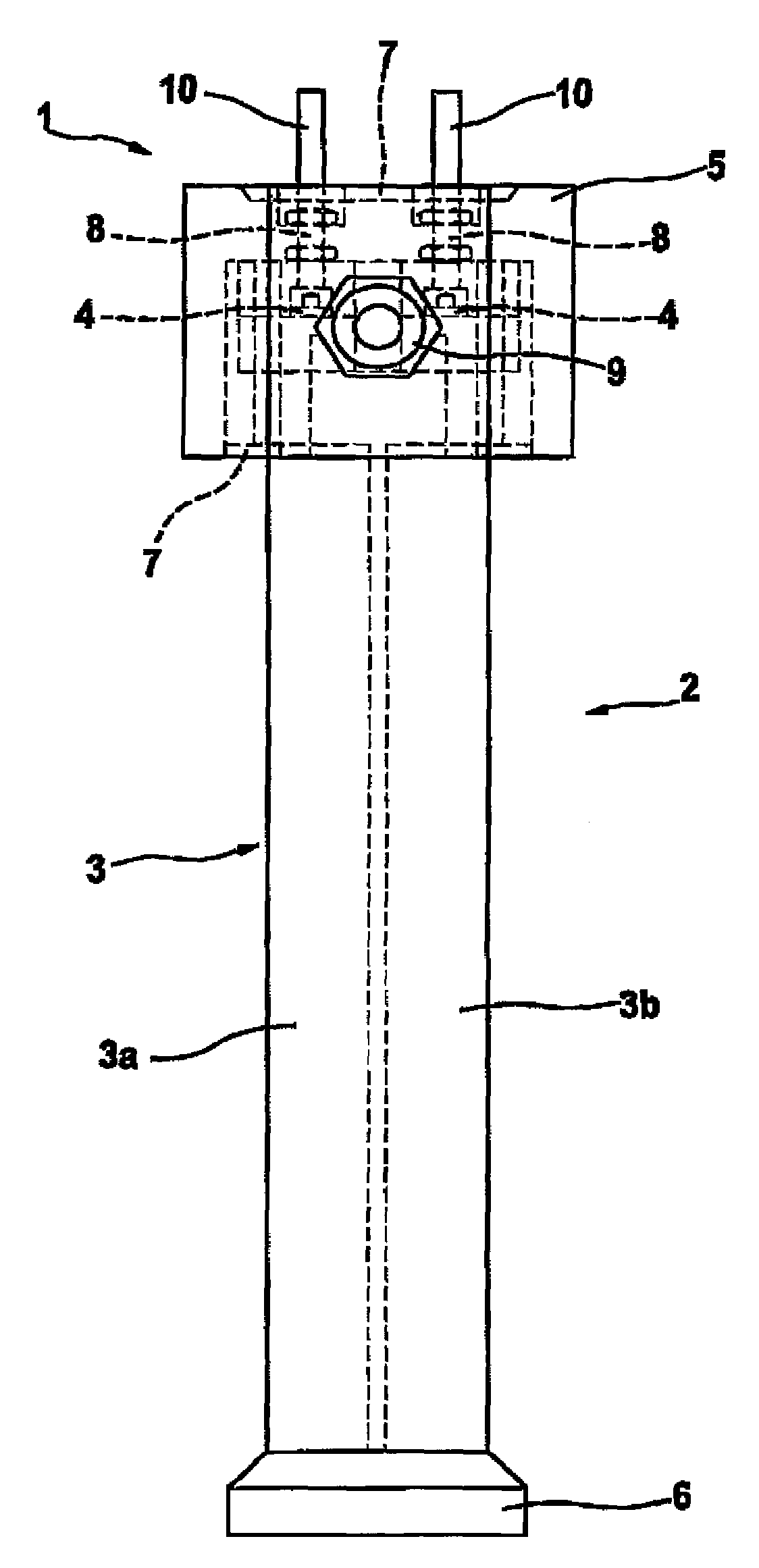
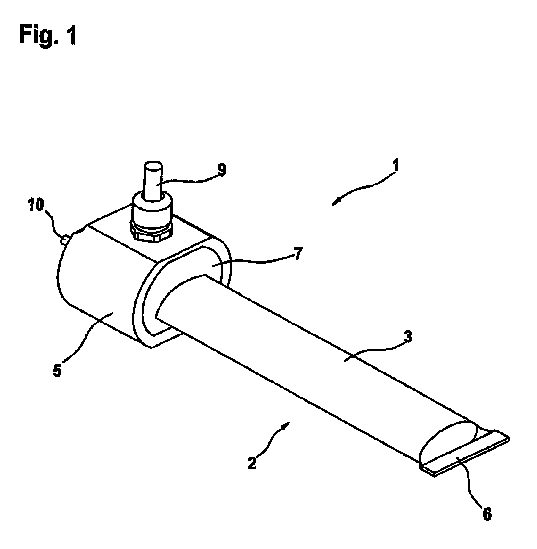
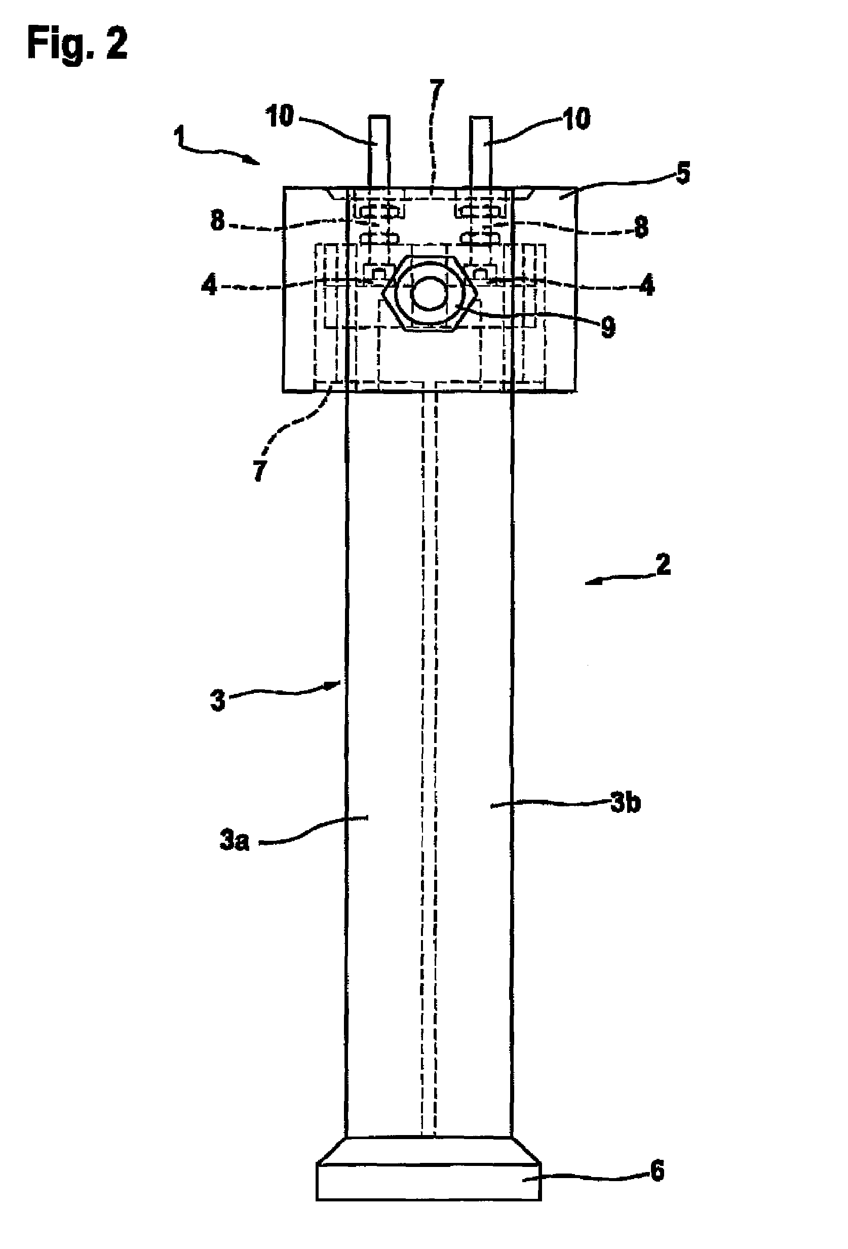
[0018]FIGS. 1 and 2 show an embodiment of a UV-C sterilizing lamp 1 of the invention.

[0019]The UV-C sterilizing lamp 1 has a UV-C emitter 2 in the form of a high-output-UV-C compact low presser emitter. The UV-C emitter 2 has an emitter foundation 3, shown here by way of example with two discharge tubes 3a, 3b, and electrical connections 4, via which the UV-C emitter 2 is connected with the base 5. The emitter foundation 3 is completely surrounded by a flexible protective cover 6, which is radiolucent to UV-C radiation and made from Teflon with a foil thickness of about 0.3 mm.

[0020]In the area of its electrical connections 4, the UV-C emitter 2 is secured in the base via a clamp (not shown), and is cast into the base 5 by means of a UV-C radiation-resistant casting material 7, in order to protect the electrical elements arranged in the base 5 from the penetration of humidity. In this embodiment the base 5 and the UV-C emitter 2 are also connected additionally via bolted connection...


PUM


Abstract

The invention relates to a UV-C sterilizing lamp for the treatment of a medium with UV-C radiation in order to kill the microorganisms contained therein by means of at least one UV-C emitter (2). The emitter has an elongated emitter foundation (3) and at least one electrical connection (4), and a base (5) holding the UV-C emitter (2). The at least the emitter foundation (3) of the UV-C emitter (2) is surrounded by a flexible protective cover (6), which is radiolucent to UV-C radiation.The invention furthermore relates to a sterilizing system with at least one UV-C sterilizing lamp of the invention.

Description

CROSS-REFERENCE TO RELATED APPLICATIONS AND CLAIM TO PRIORITY[0001]This application is based upon application number 04 028 174.3, filed Nov. 26, 2004 with the European patent Office, the disclosure of which is incorporated herein by reference and to which priority is claimed.FIELD OF THE INVENTION[0002]The present invention relates to a UV-C sterilizing lamp for the treatment of a medium with UV-C radiation in order to kill the therein contained microorganisms by means of at least one UV-C emitter, which has an elongated emitter foundation, and at least one electrical connection, as well as a base holding the UV-C emitter, as well as a UV-C emitter for the application in such a UV-C sterilizing lamp.BACKGROUND OF THE INVENTION[0003]UV-C sterilizing lamps are used for the sterilization of air in commercially and industrially used spaces as well as in hospitals and airplanes. Their germicidal UV-C line-radiation with a wavelength of λ=253.75 nm is being used to kill bacteria, fungi, ...

Claims


Application Information

Patent Timeline
Patent Type & Authority Patents(United States)
IPC IPC(8): A61N5/06
CPCA61L2/10A61L9/20F24F2003/1667F24F8/22
Inventor FERRES, MARTINKIRSTEN, MARTIN
Owner BARO GMBH & CO KG
Why Eureka
Try Eureka