Radar apparatus

a technology of radar and apparatus, applied in the field of radar apparatus, can solve the problems of low reliability of system using visible camera, inability to detect erroneously, and high cost of infrared camera compared with visible camera, so as to reduce false alarms, increase reliability, and reduce costs

Inactive Publication Date: 2008-12-09
HITACHI LTD
View PDF12 Cites 29 Cited by
  • Summary
  • Abstract
  • Description
  • Claims
  • Application Information

AI Technical Summary

Benefits of technology

[0016]The present invention has been made to solve the above problems and an object thereof is to provide an inexpensive surveillance radar apparatus capable of accurately identifying the type of an object by using a monopulse radar that performs wide-angle two-dimensional monitoring.
[0018]Also, by referencing the past measurement values of azimuthal width and correcting and outputting azimuthal width currently measured, it is possible to obtain stable output values.
[0020]This configuration reduces the cost compared with when a radar apparatus radiating waves with radiation direction varied, and also reduces false alarms to increase the reliability.
[0021]According to the present invention, it is possible to provide an inexpensive surveillance radar capable of identifying the kind of a object, by using a monopulse radar that performs wide-angle two-dimensional surveillance.

Problems solved by technology

Systems using a visible camera, however, have lower reliability when used in impenetrable bad weather or at dark night.
Those employing an infrared camera can be used any time day or night, but the infrared camera is expensive compared with the visible camera.
Also, there is an infrared-based sensor wherein a transmitter and a receiver are installed in a linear monitoring area and blocking of the infrared light to the receiver is detected, but this sensor had a problem that a flying object such as a leave and snow is erroneously detected.
However, a related radar may erroneously detect a small animal, such as a dog or cat, intruding in the monitoring area as a human, and sound an alarm or make an emergency report.
Nevertheless, the radar cross section of a detected object is not always determined precisely in an actual environment, and it is difficult to determine a detected object to be a human with this information alone.

Method used


Image

  • Radar apparatus
  • Radar apparatus
  • Radar apparatus

Examples


first embodiment

[0040]A first embodiment of the present invention is described below with reference to FIGS. 1 and 12.

[0041]First, a configuration and applications of the first embodiment of a surveillance radar of the present invention with reference to FIG. 1.

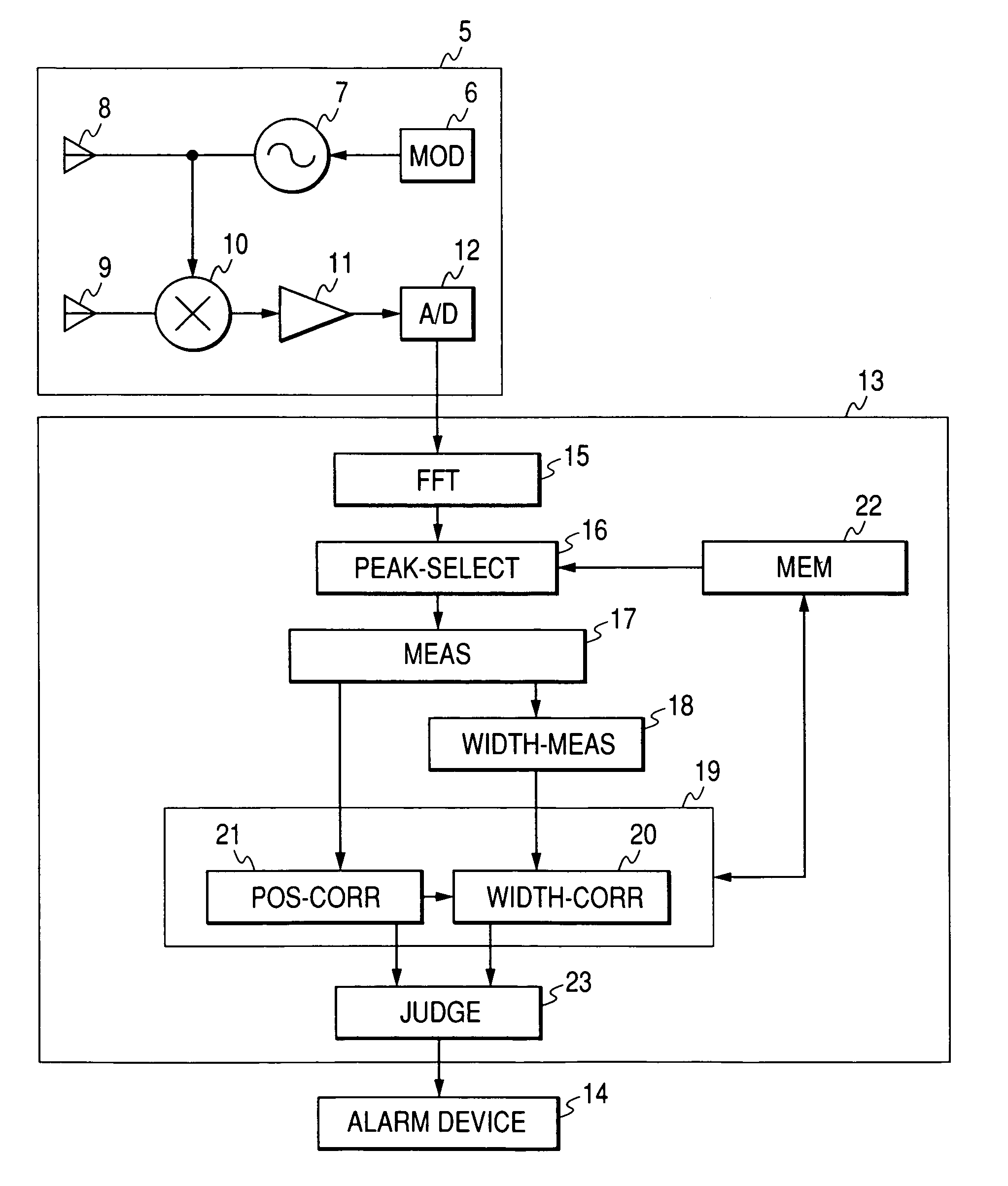
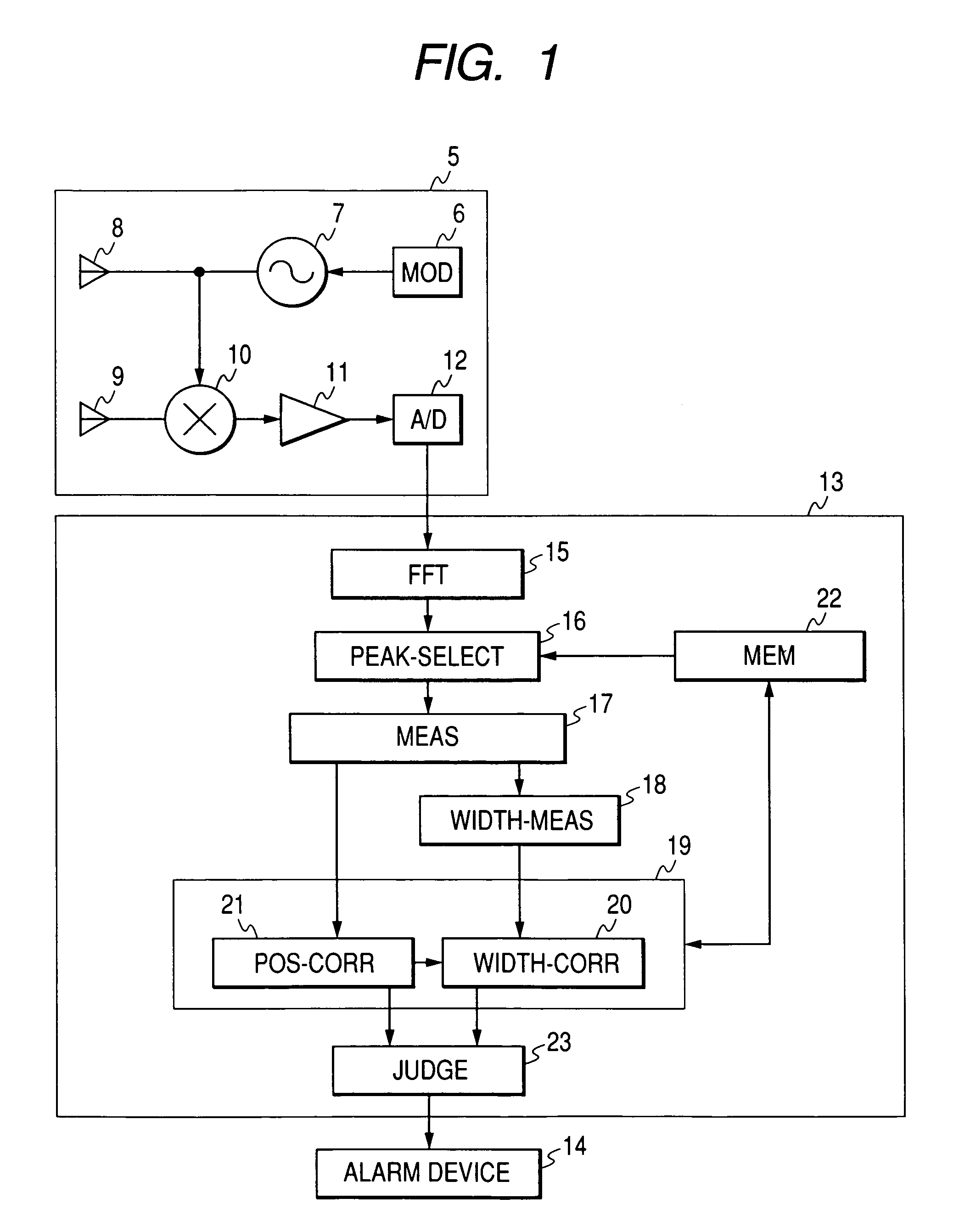
[0042]FIG. 1 is a block diagram illustrating the entire configuration of a surveillance radar of the first embodiment of the present invention.

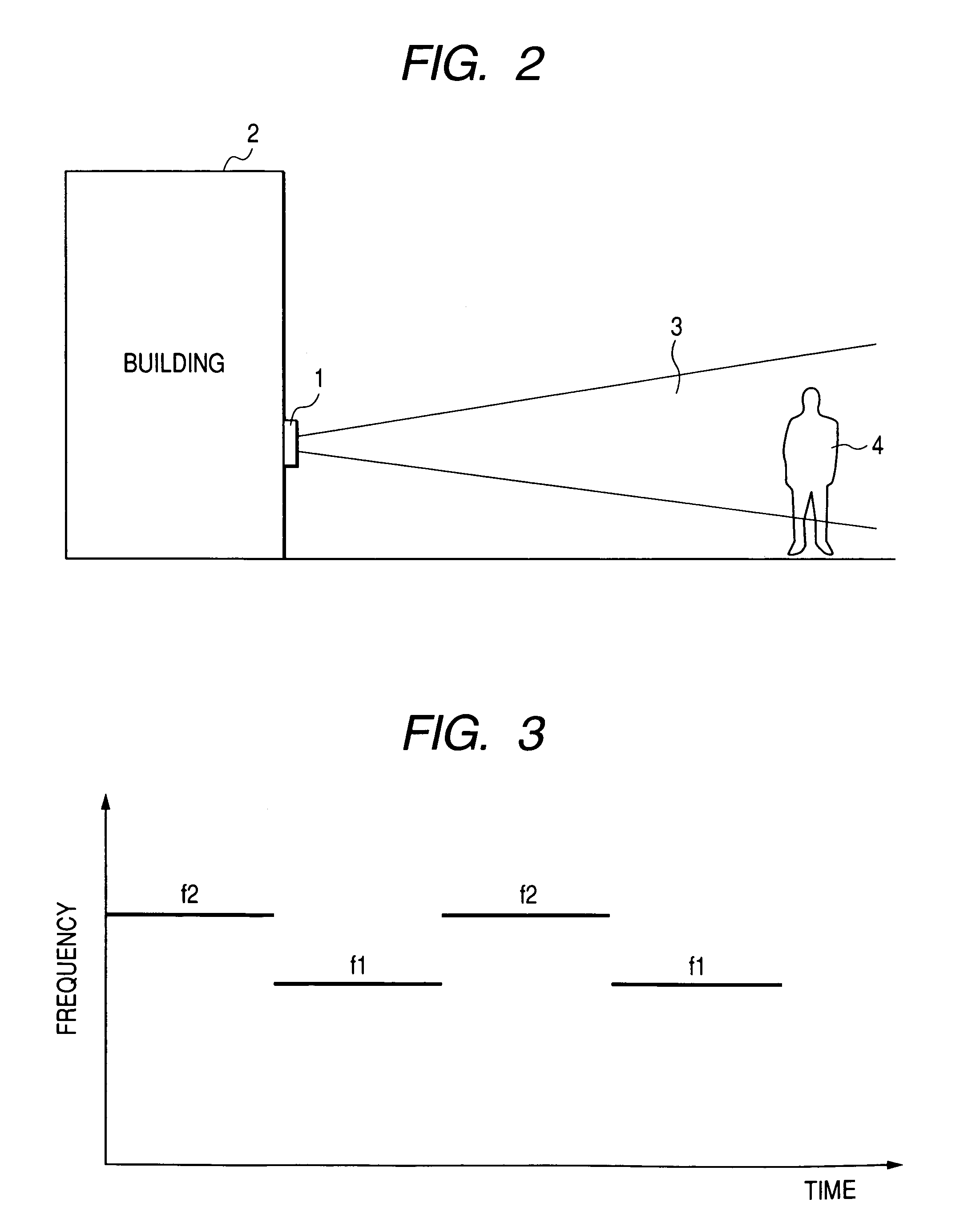
[0043]FIG. 2 is a diagram showing how a predetermined area is monitored with a surveillance radar of the first embodiment of the present invention that is installed on an outside wall of a building.

[0044]As shown in FIG. 2, a surveillance radar 1 of the present invention is applicable to an intrusion detection system for office buildings and residences. The surveillance radar apparatus 1 is installed, for example, on an outside wall of a building 2, and detects a moving object like a human intruding into a radio emission area 3. The surveillance radar apparatus 1 uses radio waves and has an advantage ...

second embodiment

[0090]Now, a second embodiment of the present invention is described below with reference to FIG. 13.

[0091]FIG. 13 is a diagram showing an example of installing a surveillance radar apparatus so that its angle measuring direction is in vertical direction.

[0092]In other words, this is an example of installing the radar apparatus with the antenna face shown in FIG. 5 of the first embodiment turned 90 degrees

[0093]Installing in this way makes it possible to measure the vertical width instead of the azimuthal width determined in the first embodiment. That is, the height of a detected object can be measured. Accordingly, if the vertical width of a detected object is within the possible values for a human, such as between 1 m and 2.5 m, the detected object identify unit 23 judges that a human walking upright is intruding, and actuates the alarm device 14 based on the judgment.

[0094]Also, using a surveillance radar apparatus of the first embodiment and that of this embodiment simultaneousl...

third embodiment

[0096]Now, a third embodiment of the present invention is described with reference to FIGS. 14 through 16.

[0097]FIG. 14 is a diagram showing an example of using a surveillance radar apparatus of the present invention by mounting the same at the front of an automobile.

[0098]FIG. 15 is a diagram showing an example of using a surveillance radar apparatus of the present invention by mounting the same at both sides of an automobile.

[0099]FIG. 16 is a diagram showing an example of using a surveillance radar apparatus of the present invention by mounting the same at the back of an automobile.

[0100]In this embodiment, the position and width of an object 34 located in front of the automobile is measured by a surveillance radar apparatus 1, and the measurement values are input to the detected object identify unit 23. The detected object identify unit 23 judges that the detected object is an automobile if the azimuthal width of a detected object is within the possible values for an automobile,...


PUM


Abstract

An inexpensive surveillance radar apparatus capable of identifying the kind of an object by using a monopulse radar that performs wide-angle two-dimensional surveillance. The radar apparatus receives reflected waves from a plurality of points on a moving object within a monitoring area, using a monopulse radar apparatus for measuring of angles, and determines the reflection point for each reflected wave, and then calculates the position and the width in the measuring angle of the surveillance radar of a moving object.

Description

CLAIM OF PRIORITY[0001]The present application claims priority from Japanese application JP 2005-344956 filed on Nov. 30, 2005, the content of which is hereby incorporated by reference into this application.FIELD OF THE INVENTION[0002]The present invention relates a radar apparatus, and more specifically to a radar apparatus suitable for use in a surveillance radar apparatus that detects an object existing within a predetermined area and monitors the movement of the same.BACKGROUND OF THE INVENTION[0003]JP 2000-338231 A describes an art related to a radar apparatus that detects an intruding object by utilizing a radiowave such as microwave.[0004]Also, JP 2002-236171 A discloses a radar system that detects an intruding object, and determines whether the intruding object is a human body or not, based on the radar cross section calculated from the signal power.[0005]Further, JP 1999-183612 A describes a vehicle-mounted radar system, a signal processing circuit of which determines a dis...

Claims


Application Information

Patent Timeline
Patent Type & Authority Patents(United States)
IPC IPC(8): G01S13/42
CPCG01S7/415G01S13/38G01S13/4445G01S13/536G01S13/931G01S2013/9385G01S13/886G01S2013/9375G01S2013/9378G01S13/584G01S2013/93271G01S2013/93272G01S2013/93274
Inventor MORINAGA, MITSUTOSHINAGASAKU, TOSHIYUKI
Owner HITACHI LTD
Why Eureka
Try Eureka