Polyphase hydraulic drive system

a hydraulic drive system and polyphase technology, applied in the direction of rotary clutches, fluid couplings, gearings, etc., can solve the problems of valve system inefficiency, valve system design complexity, maintenance, etc., and achieve the effect of smooth repositioning

a hydraulic drive system and polyphase technology, applied in the direction of rotary clutches, fluid couplings, gearings, etc., can solve the problems of valve system inefficiency, valve system design complexity, maintenance, etc., and achieve the effect of smooth repositioning

US7464549B1Inactive Publication Date: 2008-12-16BOREALIS TECH LTD

Image

  • Polyphase hydraulic drive system
  • Polyphase hydraulic drive system
  • Polyphase hydraulic drive system

Examples


Embodiment Construction

[0036]An embodiment of the present invention and its advantages are best understood by referring in more detail to FIGS. 1 through 7, in which like numerals refer to like parts throughout.

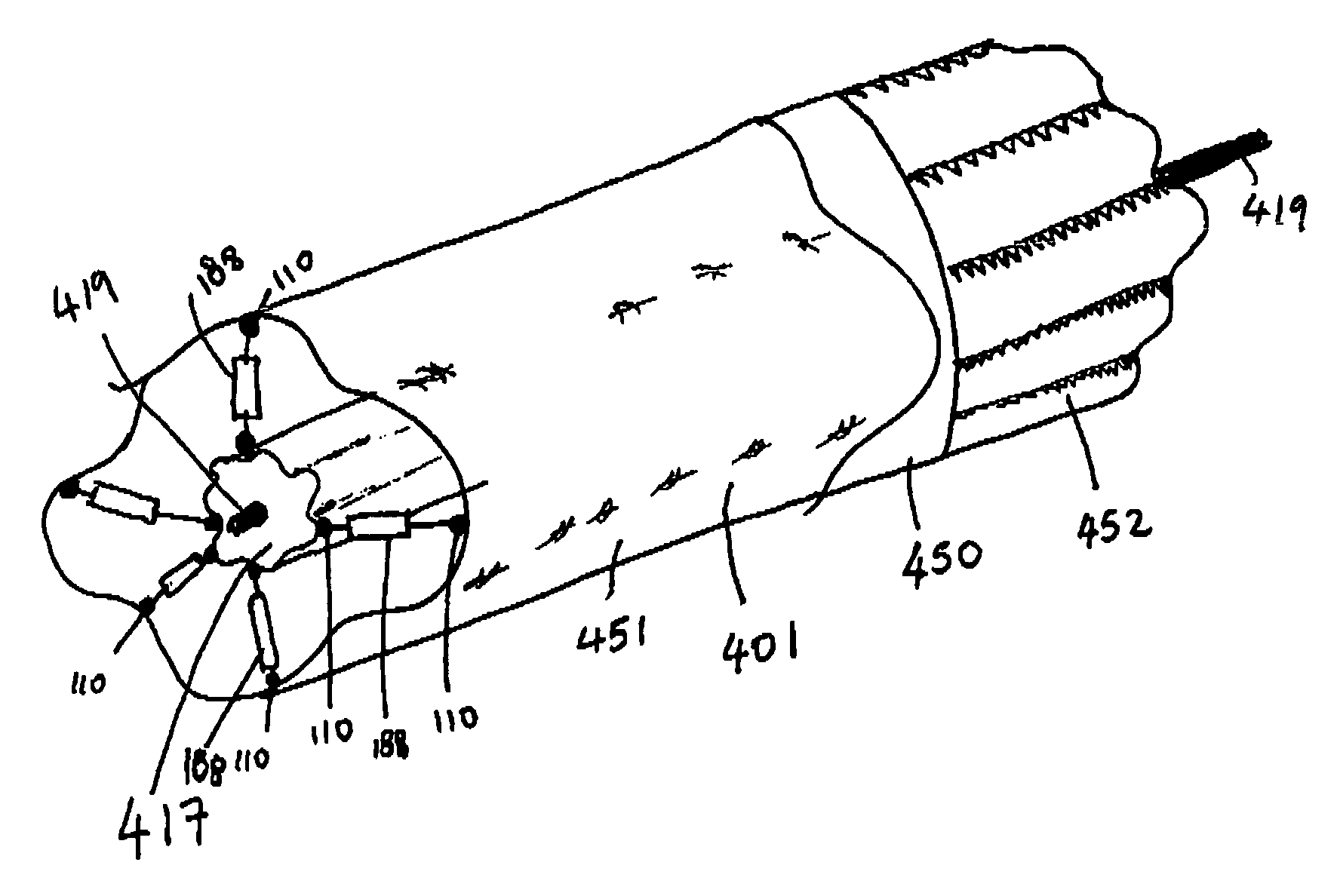
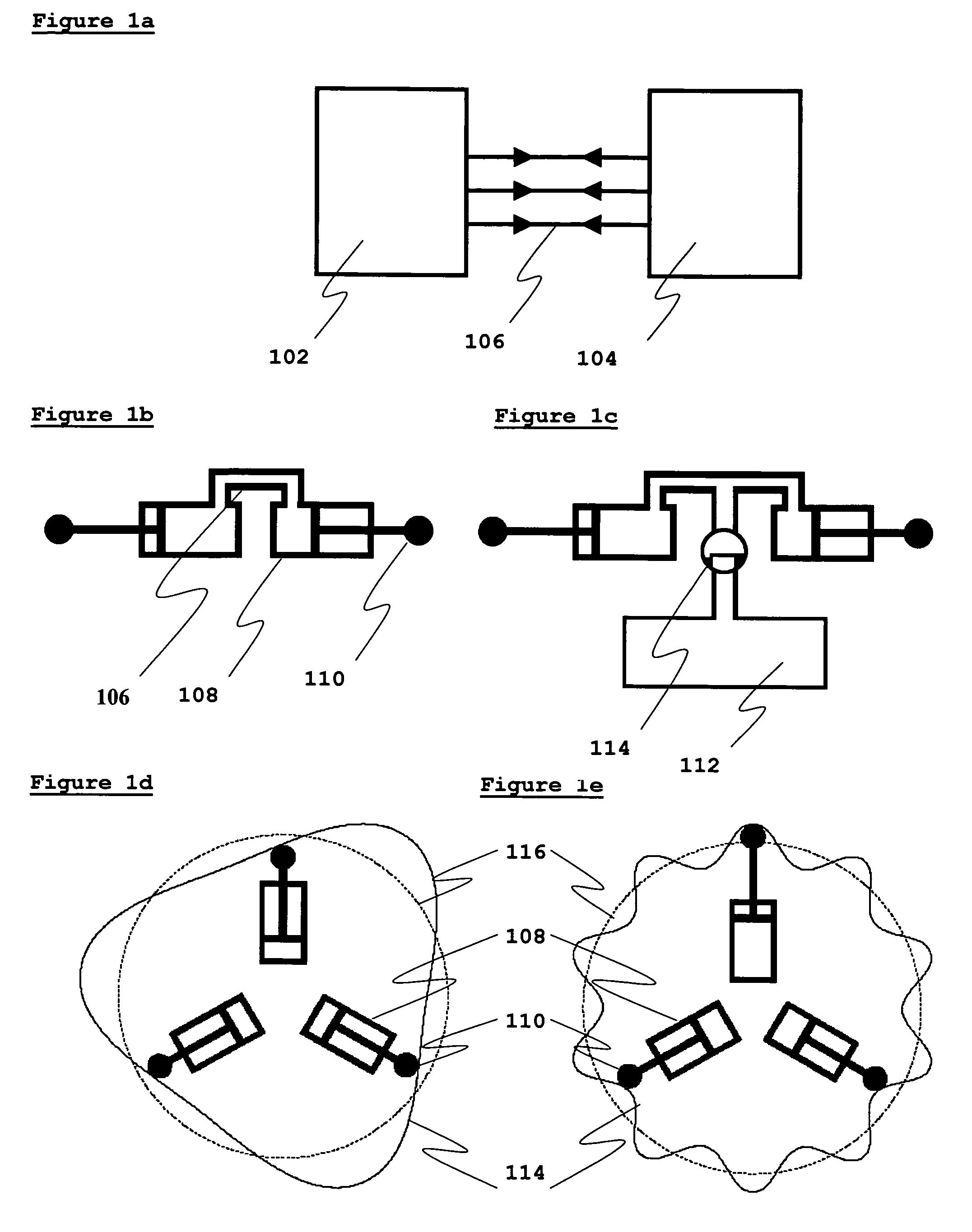
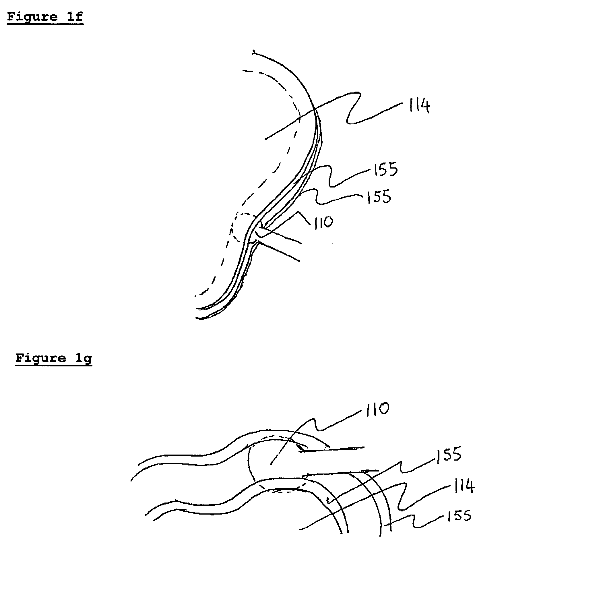
[0037]Referring now to FIG. 1a, which shows a simple schematic of the present invention, input drive system 102 and output drive system 104, both including hydraulic elements. Input drive system 102 and output drive system 104 are connected by hydraulic lines 106. In this example, the input drive system produces three phases of oscillating fluid output, and hydraulic lines 106 consist of three fluid lines, which independently and directly feed these three phases of oscillating fluid output to the output drive system. Thus the drive and driven pistons are directly coupled by the hydraulic fluid. The connection between the hydraulic elements on the input drive side and the output drive side may be achieved in a number of ways known to the art. For example, as shown in FIG. 1b, the hydraulic elements ...


PUM


Abstract

The present invention comprises an input drive system, which provides a plurality of phases of oscillating fluid flow, and an output drive system connected directly to the input drive system that is powered by the plurality of phases of oscillating fluid flow. The input drive system comprises a plurality of pistons that are caused to move in a reciprocating fashion by a power source. The power source may be a rotating power source, such as that provided by an electric motor, a diesel or petrol engine, or a turbine system. The input drive system comprises a cam ring attached to a rotating power source; a plurality of cam rollers in contact with the cam ring; and a plurality of pistons attached to the cam rings. The output drive system comprises one or more pistons that are caused to move in a reciprocating fashion by the oscillating fluid flow provided by the input drive system. The output drive system comprises a cam ring attached to a load; a plurality of cam rollers in contact with the cam ring; and a plurality of pistons attached to the cam rings.

Description

CROSS-REFERENCE TO RELATED APPLICATIONS[0001]This application claims the benefit of U.S. Provisional Application No. 60 / 641,622, filed Jan. 4, 2005.BACKGROUND OF THE INVENTION[0002]The present invention relates to hydraulic drive systems for gear-less inter-conversion of rotational energy and gear-less conversion of rotational energy to linear kinetic energy.[0003]Henricson (U.S. Pat. No. 5,657,681) discloses a hydraulic drive system comprising a plurality of hydraulically driven piston units with cam rollers, which are disposed to act against a lobed cam profile of a cam curve element, so that linear movement of the cam rollers against the cam profile produces a relative driving movement between the cam element and the piston units. The characterizing feature of the invention is that the drive system is composed of separate, assembled cam curve element modules and separate assembled piston units.[0004]Reboredo (U.S. Pat. No. 5,689,956) discloses a hydraulic variable speed drive ass...

Claims


Application Information

Patent Timeline
16 Dec 2008
Publication
US7464549B1
IPC
F15B7/02
CPC
F15B7/008; F15B7/02; F16H39/16; F16H39/18
Inventors
EDELSON, JONATHAN SIDNEY; COLLIER, WAYNE BOYER