Electrical connector having a fluid coupling

a technology of fluid coupling and electric connector, which is applied in the direction of coupling device connection, coupling device details, connection contact member materials, etc., can solve the problems of not carrying the desired flow rate, overly complex connection of internal tubing system to external source of fluid, and more difficult to assemble and/or repair fluid couplings of such structures

Active Publication Date: 2008-12-16
TYCO ELECTRONICS LOGISTICS AG (CH)
View PDF19 Cites 24 Cited by
  • Summary
  • Abstract
  • Description
  • Claims
  • Application Information

AI Technical Summary

Problems solved by technology

However, connecting the internal tubing system to the external source of fluid may be overly complex and / or difficult for some support structures and / or electronic devices.
Such support structures may therefore be restricted to using fluid couplings below a predetermined size, which may not carry a desired flow rate.
It may also be more difficult to assemble and / or repair the fluid couplings of such structures because of the limited space.

Method used


Image

  • Electrical connector having a fluid coupling
  • Electrical connector having a fluid coupling
  • Electrical connector having a fluid coupling

Examples


Embodiment Construction

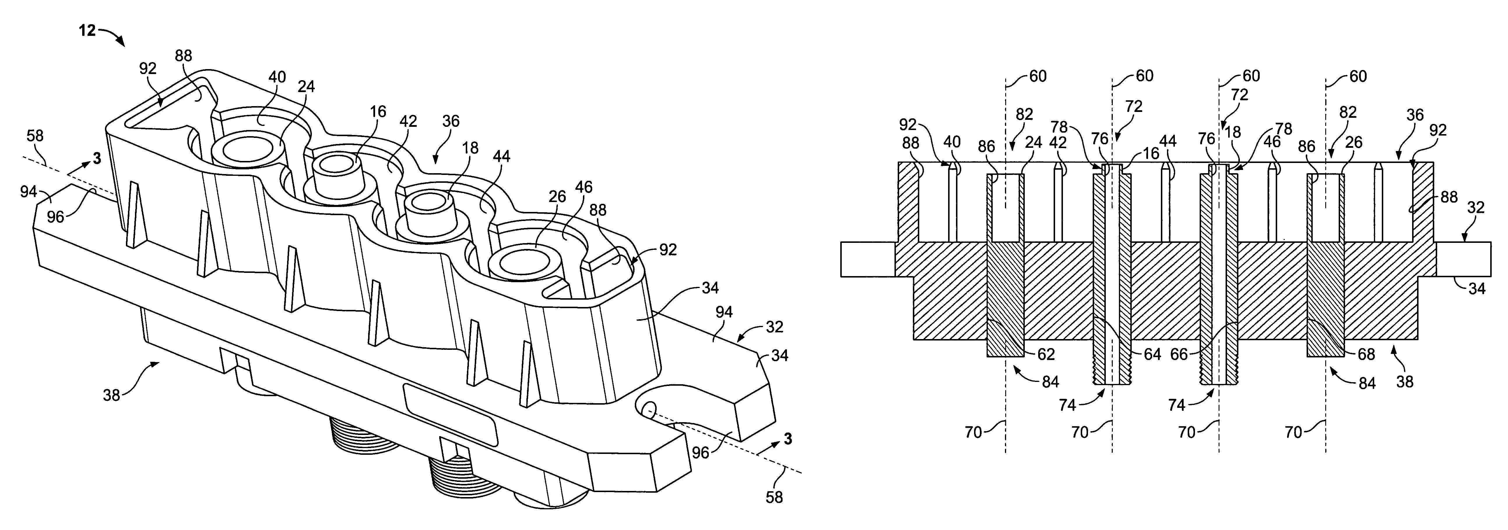
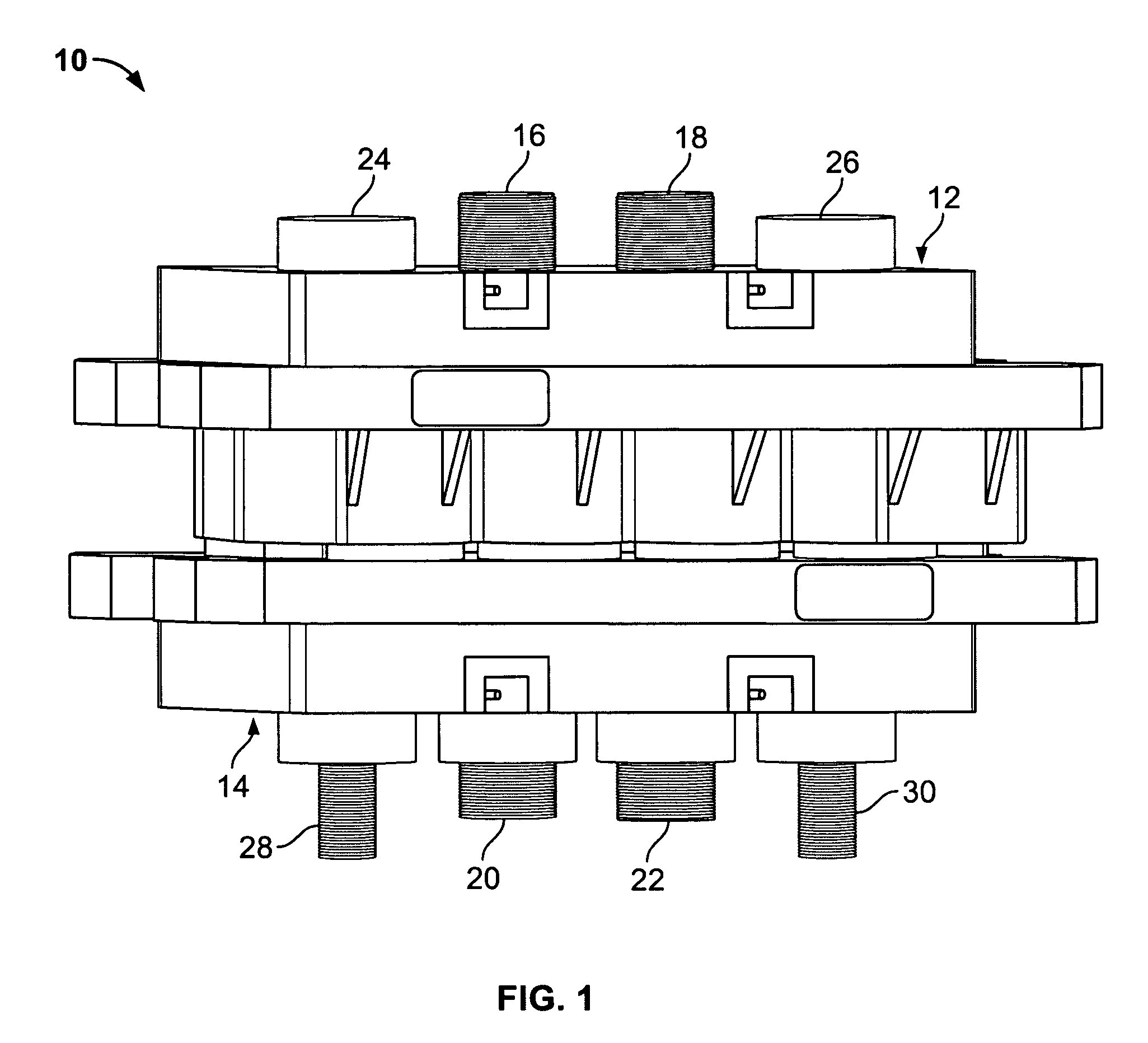
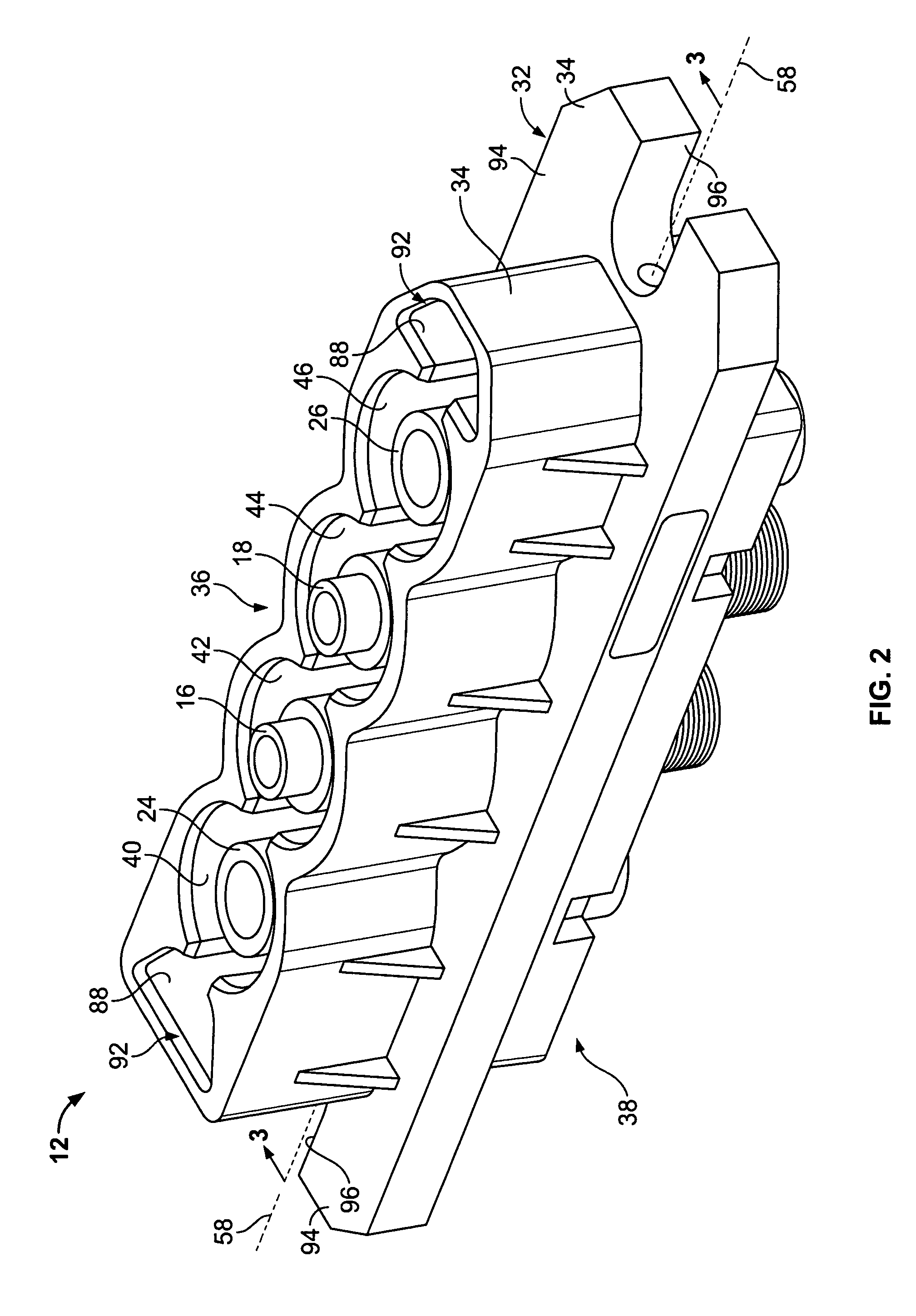
[0012]FIG. 1 is a perspective view of an electrical connector assembly 10 formed in accordance with an embodiment of the present invention. The connector assembly 10 includes a pair of electrical connectors 12 and 14 that are configured to be connected to one another, as shown in FIG. 1. The connectors 12 and 14 may each be referred to herein as a first and / or a second connector. As will be described in more detail below, the connector 12 includes a pair of fluid couplings 16 and 18 that each engage a respective fluid coupling 20 and 22 of the connector 14 for carrying flow of a fluid through the connector assembly 10. The fluid couplings 16, 18, 20, and 22 may each be referred to herein as a first and / or a second fluid coupling. The fluid may be used to cool electrical and / or other components (not shown) that are connected, whether electrically or mechanically, to the connector assembly 10, electrical and / or other components that are adjacent the connector assembly 10, and / or elect...


PUM


Abstract

An electrical connector includes a housing having a mating end, a rear end opposite the mating end, and first and second openings each extending from the mating end to the rear end. An electrical contact is held at least partially within the first opening. A fluid coupling is held at least partially within the second opening. The fluid coupling includes a body having a fluid passageway extending therethrough. The fluid passageway is configured to carry flow of a fluid between the mating and rear ends of the housing.

Description

BACKGROUND OF THE INVENTION[0001]The invention relates generally to electrical connectors and, more particularly, to an electrical connector having a fluid coupling.[0002]Many electronic devices are cooled to remove heat generated during their operation. Cooling of electronic devices may sometimes be accomplished by circulating a flow of a fluid, such as water, through, around, and / or adjacent to the electronic device(s). To deliver the fluid into, around, and / or adjacent to the electronic device(s), the fluid is often circulated through an internal system of tubing that extends within one or more support structures, such as a chassis, which support the electronic device(s). The fluid is supplied from a source connected to the system of tubing, which is often located external to the support structure(s).[0003]However, connecting the internal tubing system to the external source of fluid may be overly complex and / or difficult for some support structures and / or electronic devices. For...

Claims


Application Information

Patent Timeline
Patent Type & Authority Patents(United States)
IPC IPC(8): H01R4/60
CPCH01R13/005
Inventor WOOD, DONALD EVERETT
Owner TYCO ELECTRONICS LOGISTICS AG (CH)
Why Eureka
Try Eureka