Method of fixing components

a fixing system and component technology, applied in the field of fixing systems, can solve the problems of unreliable, high rejection rate, and relatively high production cost of fixing systems of this kind, and achieve the effects of high quality, easy and cheap production, and maintaining pre-stressing

Inactive Publication Date: 2008-12-23
DECOMA GERMANY
View PDF5 Cites 4 Cited by
  • Summary
  • Abstract
  • Description
  • Claims
  • Application Information

AI Technical Summary

Benefits of technology

[0007]It is desirable to overcome these problems by providing a simple, cheaply produced and reliable fixing system particularly for securing motor vehicle components to one another.
[0008]The fixing system according to the invention can be produced easily and cheaply and has proved to be robust and reliable in practice. Using the system according to the invention it is possible to clip plastic components together with virtually no play and in such a way as to maintain pre-stressing. As the system merely comprises components which are to be formed on the components to be fixed to one another, no additional fixing elements are required. The system according to the invention can be produced to a very high quality as production is well controlled and can be mounted and dismantled several times. The system according to the invention provides the same operational reliability as conventional known systems while making mounting and dismantling easier.
[0009]According to a first preferred embodiment of the system according to the invention, two, three, four or more tabs are formed on the first component to be secured, engaging with a corresponding number of tongues provided on the second component. By matching the number of tabs and tongues which are to engage with one another the fixing system according to the invention can easily be adapted to the size or mass of the components which are to be fixed together.

Problems solved by technology

A fixing system of this kind has proved to be relatively expensive to produce and unreliable.
Moreover there is a relatively high number of rejects.

Method used


Image

  • Method of fixing components
  • Method of fixing components
  • Method of fixing components

Examples


Embodiment Construction

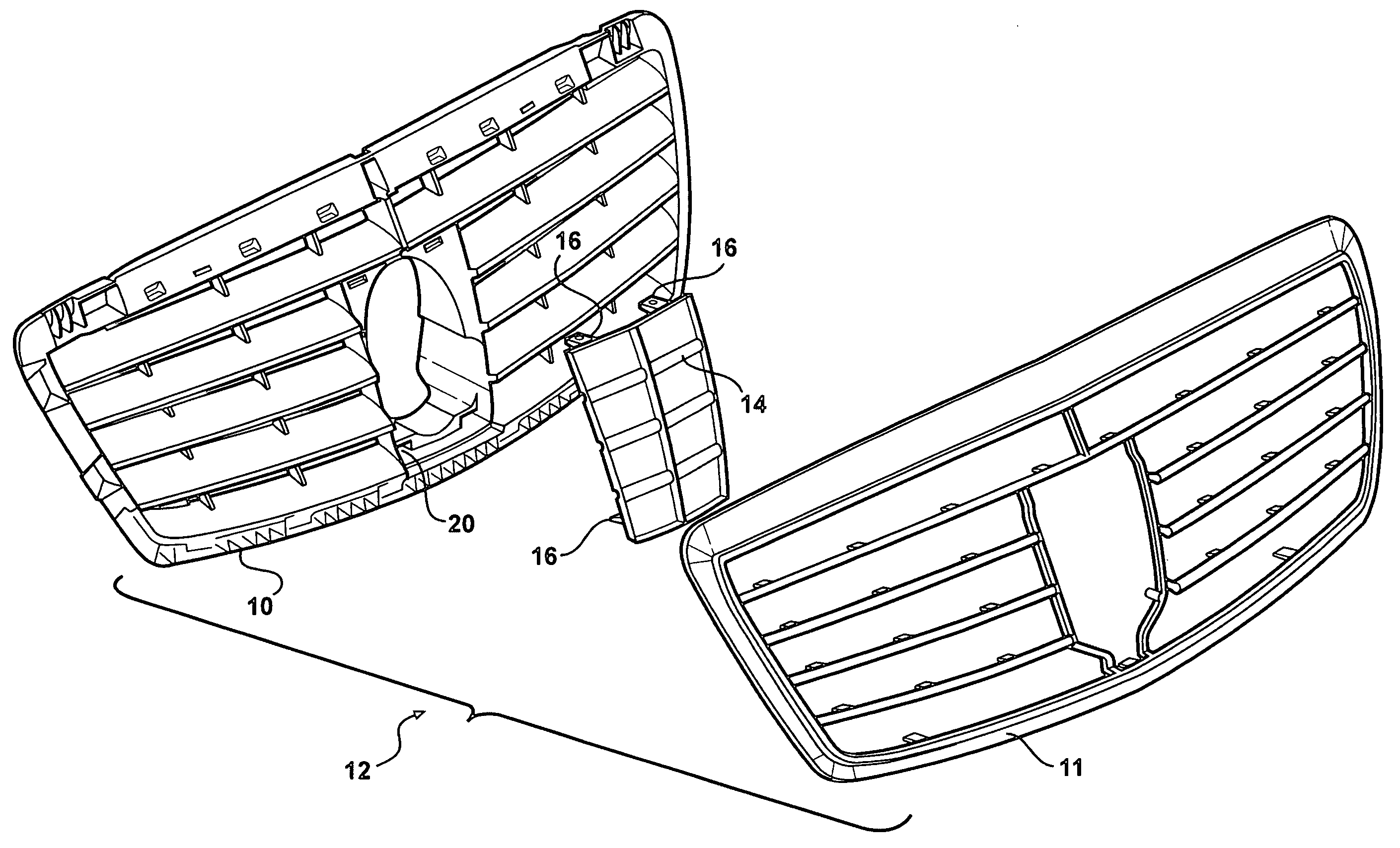
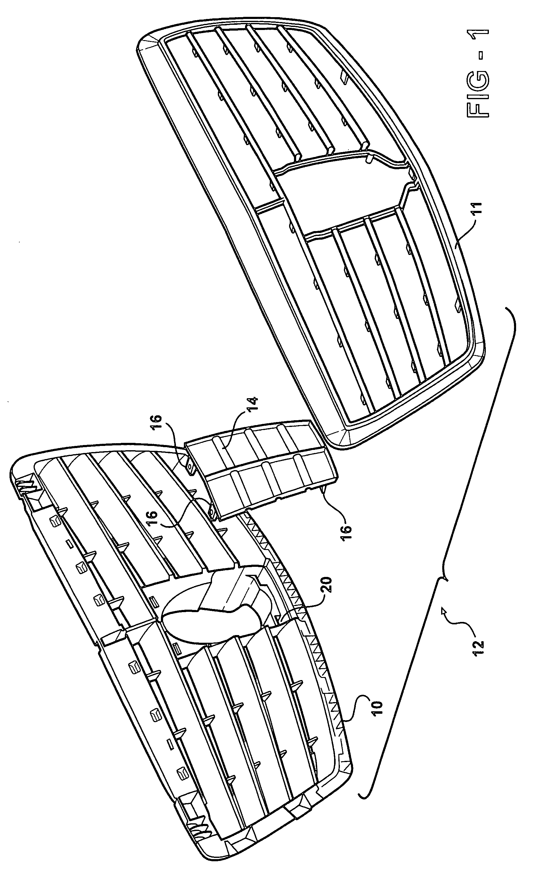
[0020]In FIG. 1, a radiator grille including a plurality of components 10, 11 and 14 is generally designated at 12. The component 10 of the radiator grille 12 is a radiator mesh while component 11 is a frame. The component 14 is a distance control plate 14, to be used within the scope of a distance regulating or control device, is to be fixed to the radiator mesh 10

[0021]It should be pointed out that it is possible to secure the components 10 and 11 to one another first and then to fix the distance control plate 14 to the radiator grille thus formed, using the system according to the invention.

[0022]However, in the interests of simplicity and by way of example, it will be assumed here that the distance control plate 14 is first fixed to the radiator mesh 10 and then the frame 11 is mounted on the components 10, 14 fixed to one another.

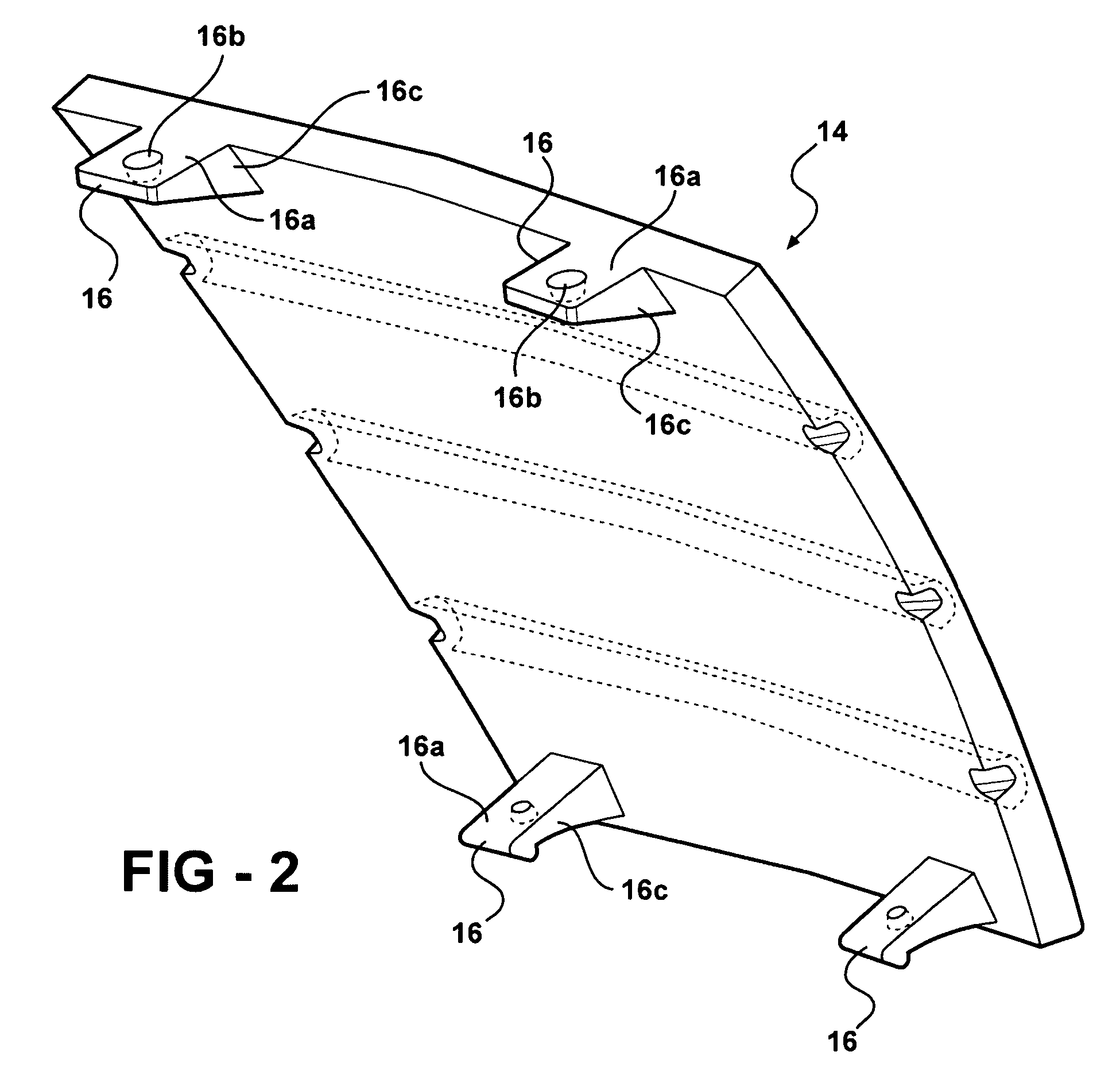
[0023]The distance control plate 14 is constructed with four tabs 16 which are also clearly shown in FIG. 2. The tabs 16 each have a substantially pla...


PUM

PropertyMeasurementUnit
diameteraaaaaaaaaa
distanceaaaaaaaaaa
timeaaaaaaaaaa

Abstract

A method of fixing a first component to a second component. The method includes the step of arranging the first component adjacent the second component. Aligning a tab of the first component for selective engagement with a tongue of the second component. Sliding the first component longitudinally against the second component. Flexing the tongue of the second component by sliding the tab of the first component longitudinally along a conical projection of the second component. Overlapping the tongue and the tab until the conical projection is axially aligned with and matingly received and retained in a conical hole in a direction generally orthogonal to the longitudinal sliding movement thereby selectively fixing the first component to the second component.

Description

RELATED APPLICATIONS[0001]This application is a divisional application of U.S. application Ser. No. 10,397,558 filed on Mar. 27, 2003 now abandoned.BACKGROUND OF THE INVENTION[0002]1. Field of Invention[0003]The present invention relates to a fixing system for fixing a first component to a second component.[0004]2. Description of the Related Art[0005]In the field of automobile construction, in particular, there is frequently a need to fix individual components to one another. Examples include interior cladding sections which are to be mounted on corresponding support members of the bodywork. Another example is the exterior mounting of decorative strips on the vehicle bodywork.[0006]It is also necessary from time to time to fix components to the radiator grille of a motor vehicle. Thus, for example, it is known to fix a so-called distance control plate or ART plate to a radiator grille within the scope of distance sensing and regulating technology (German: Abstands-Regel-Technik, ART...

Claims


Application Information

Patent Timeline
Patent Type & Authority Patents(United States)
IPC IPC(8): B23P11/02B60R19/52F16B5/06
CPCB60R19/52F16B5/0635B60R2019/525F16B5/0621Y10T29/49876Y10T29/49869Y10T29/49895Y10T403/606
Inventor AIGNER, ALIOTTE, HERMANN
Owner DECOMA GERMANY
Why Eureka
Try Eureka