
Compression spring rod

a compression spring and rod body technology, applied in the direction of shock absorbers, wing accessories, wound springs, etc., can solve the problems of premature failure, subsequent loss of spring life, loss of control forces, etc., and achieve the effect of reducing load loss over tim

Inactive Publication Date: 2008-12-23
BARNES GROUP
View PDF38 Cites 13 Cited by
  • Summary
  • Abstract
  • Description
  • Claims
  • Application Information

AI Technical Summary

Benefits of technology

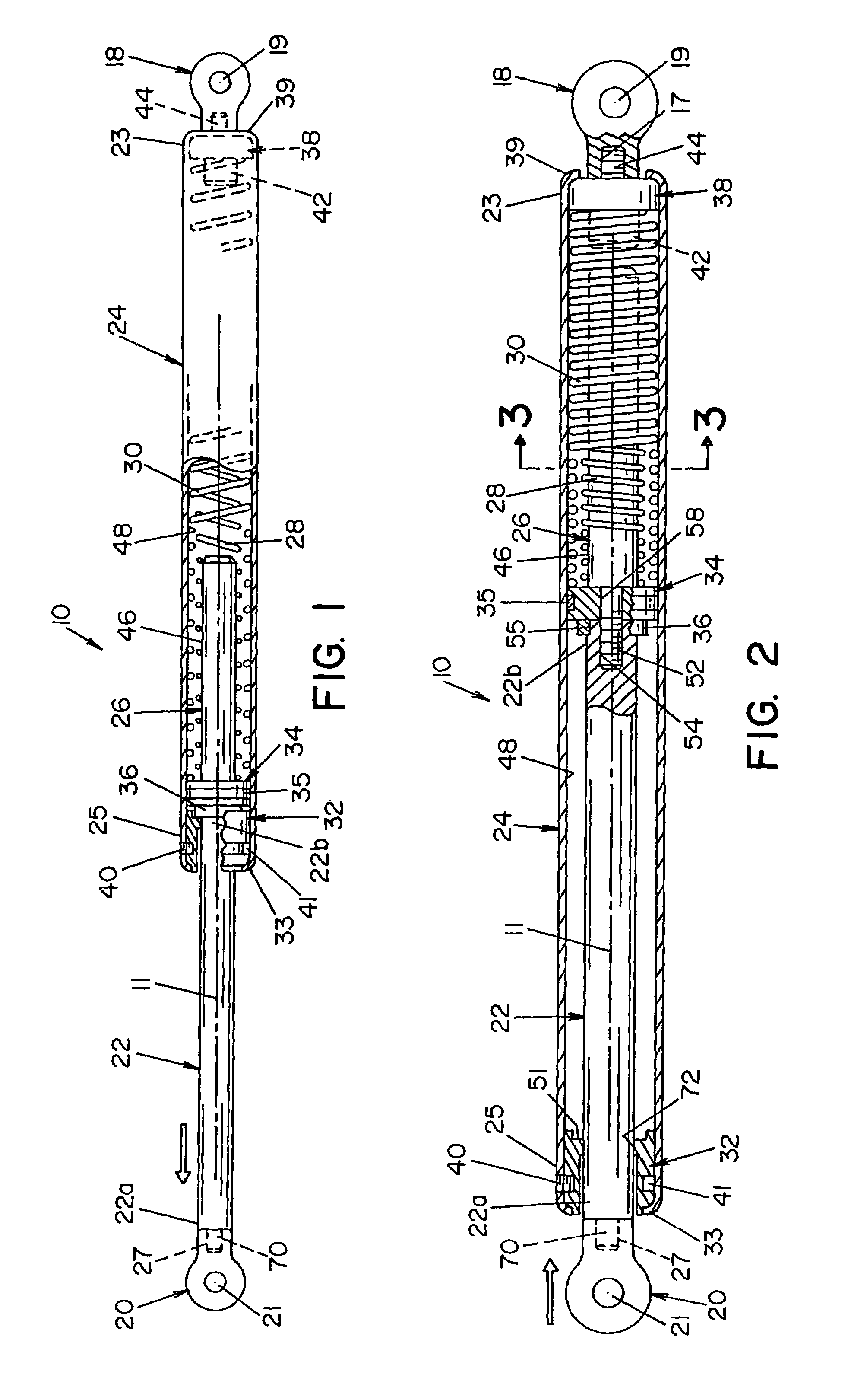
[0006]A compression spring rod according to the invention is comprised of multiple compression springs. The compression spring rod assembly includes a rod which is adapted to extend and retract relative to a housing. In one application, for example, the compression springs will build potential force as the springs are compressed, and release that force once the springs are allowed to expand. This extension of the springs imparts a force to the parts connected to the ends of the rod and housing and, advantageously, multiple end configurations can be used to adapt the spring rod to a variety of mounting applications. The compression springs of a spring rod according to the invention are interrelated to produce a linear load versus deflection curve. The encased springs minimize load losses over time, and the mechanism does not contain any fluid or gases within the lift body. This advantageously eliminates the inevitable problem of leakage and subsequent loss of utility.
[0007]It is accordingly an outstanding object of the present invention to provide an improved compression spring rod for exerting an operating force on a displaceable member at a controlled rate.
[0010]Yet another object of the invention is the provision of a compression spring rod having at least two compression springs interrelated to minimize load losses over time.

Problems solved by technology

Consequently, because these products contain a gas and / or fluid, they are subject to premature failure, due to the leakage of the gas or fluid over time.
The leakage results in a loss of control forces and a subsequent loss of spring life.

Method used


Image

  • Compression spring rod
  • Compression spring rod
  • Compression spring rod

Examples


Embodiment Construction

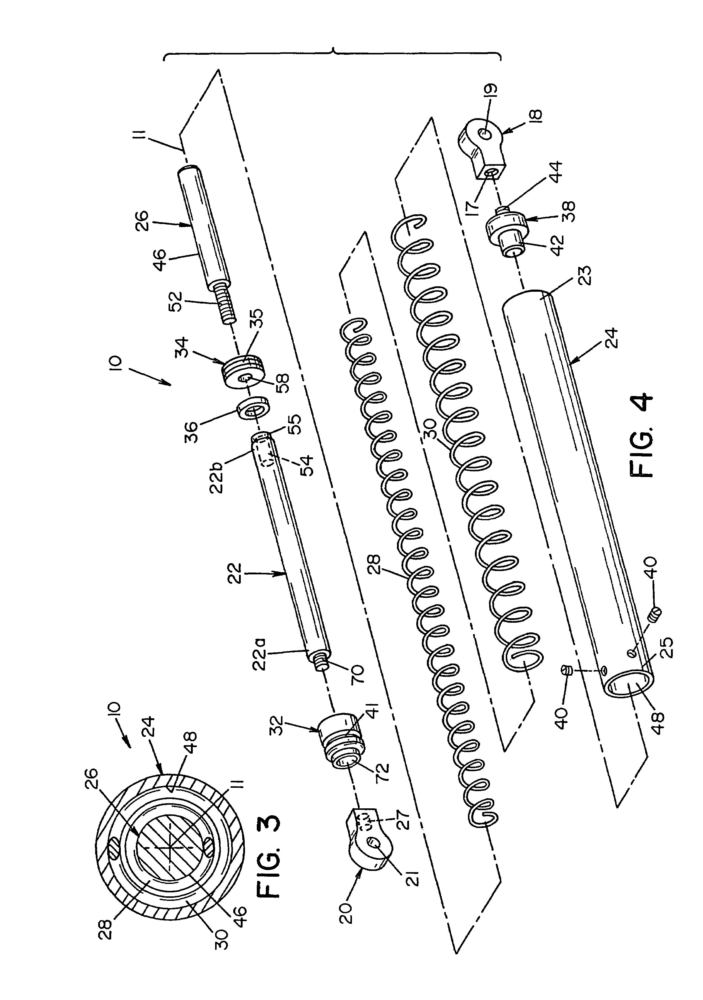
[0027]Referring now in greater detail to the drawings, wherein the showings are for the purpose of illustrating preferred embodiments of the invention only, and not for the purpose of limiting the invention, a compression spring rod 10, in accordance with the invention, as shown in FIGS. 1-6, has an axis 11 and includes a rod member 22 which is axially extendable and retractable relative to a one-piece tubular housing 24. Rod 22 has an outer end 22a and an inner end 22b connected to a guide rod 26 as set forth more fully hereinafter. Guide rod 26 extends axially inwardly of inner end 22b of rod 22 and is surrounded by a first compression spring 28 which is supported by the exterior surface 46 of guide rod 26 against buckling. First compression spring 28 is surrounded by a second compression spring 30 which is supported against buckling by the interior surface 48 of housing 24. Alignment of compression springs 28 and 30 relative to one another and axis 11 is maintained by the exterio...


PUM


Abstract

A compression spring rod for relatively displacing elements attached to end mounts of the rod assembly comprises a housing having a rod member moveable between extended and retracted positions relative thereto, and a first compression spring in the housing surrounded by a second compression spring for biasing the rod member to one of an extended or retracted position relative to the housing. The two springs are oppositely wound, of different length, of different outside diameter, and of different wire diameter whereby, from a compressed condition, the spring rod exerts an expansion force which increases at a linear rate. Two sets of the springs can be arranged for biasing the rod member to a central position relative to the housing.

Description

[0001]This patent application is a continuation of U.S. application Ser. No. 10 / 056,941 filed Jan. 28, 2002 now U.S. Pat. No. 6,773,002.BACKGROUND OF THE INVENTION[0002]The present invention relates to compression spring rods, and more particularly, to a spring and rod assembly that exerts an expansional force which increases at a linear rate.[0003]The invention relates to a mechanism for biasing hoods, tops, doors, hinged covers, and other elements from a closed to an open position. The invention involves the use of springs in conjunction with a rod member to exert the driving force on the elements to be displaced. The following patents are incorporated herein by reference as background information with regard to spring mechanisms: U.S. Pat. No. 6,199,843 to DeGrace; U.S. Pat. No. 5,810,339 to Küspert, et al.; and U.S. Pat. No. 4,962,916 to Palinkas.[0004]Compression spring rods are used in various applications, for example, to assist in lifting, opening, and damping. Typical appli...

Claims


Application Information

Patent Timeline
Patent Type & Authority Patents(United States)
IPC IPC(8): F16F1/12F16F1/06E05F1/10E05F3/02E05F3/10F16F3/04F16F9/00F16F9/19F16F9/20F16F9/32
CPCF16F3/04F16F3/02
Inventor ADOLINE, JACK W.FISCHER
Owner BARNES GROUP
Learn More