Lip-type seal

a type of seal and a technology of a sleeve, applied in the direction of engine seals, mechanical devices, engine components, etc., can solve the problems of reducing durability and increasing wear of the sleeve, and achieve the effect of further improving durability and abrasion resistan

Inactive Publication Date: 2008-12-23
EAGLE INDS +1
View PDF15 Cites 15 Cited by
  • Summary
  • Abstract
  • Description
  • Claims
  • Application Information

AI Technical Summary

Benefits of technology

[0010]According to this structure, the lip part of the seal ring in an area deviating from the supporting part of the support ring is appropriately deformed and brought into contact with the shaft in a state of having a greater contact width with the shaft when the lip part of the seal ring is exposed to a high-pressure environment. Hence, appropriate surface pressure under which sealability is secured is obtained, and the surface pressure is dispersed to lower a maximum surface pressure. As a result, wear of the lip part is reduced, and durability is improved.
[0012]According to this structure, since the lip part of the seal ring in an area deviating from the supporting part of the support ring is formed to have a thickness satisfying the condition (α=0.3 to 0.7), bending strength of the lip part in its entirety is uniform, and partial wear can be prevented. Therefore, sealability and durability are further improved.
[0014]According to this structure, since the end of the lip part is formed to have a tightening margin satisfying the condition (β=0.03-0.15), partial wear can be prevented, and sealability and durability are further improved.
[0016]According to this structure, since the lip part of the seal ring in the area deviating from the supporting part of the support ring is formed to have a thickness satisfying the condition (α=0.3 to 0.7), and since the tip end of the lip part is formed to have a tightening margin satisfying the condition (β=0.03-0.15), bending strength of the lip part in its entirety is uniform, and partial wear can be prevented even more effectively. Therefore, sealability and durability are further improved.
[0018]According to this structure, since a bent supporting part of the support ring supports the lip part of the seal ring by a not partially but uniformly gently curved surface, the lip part is urged to be deformed with a gentle slope in a high-pressure environment, and the contact surface pressure can be made more uniform.
[0020]According to this structure, a contact state between the lip part of the seal ring and the shaft can be kept optimum, and abrasion resistance and durability are further improved.

Problems solved by technology

Therefore, a conventional problem resides in that the lip part 1b is increasingly worn out, and durability is lowered in spite of the fact that the lip part 1b is supported by the support ring 2.

Method used


Image

  • Lip-type seal
  • Lip-type seal
  • Lip-type seal

Examples


Embodiment Construction

[0031]Preferred embodiments of the present invention will be hereinafter described with reference to the attached drawings. Herein, a description will be given of a case in which a lip-type seal according to the present invention is used in an air conditioning compressor serving as a part of an air conditioning system of, for example, a vehicle.

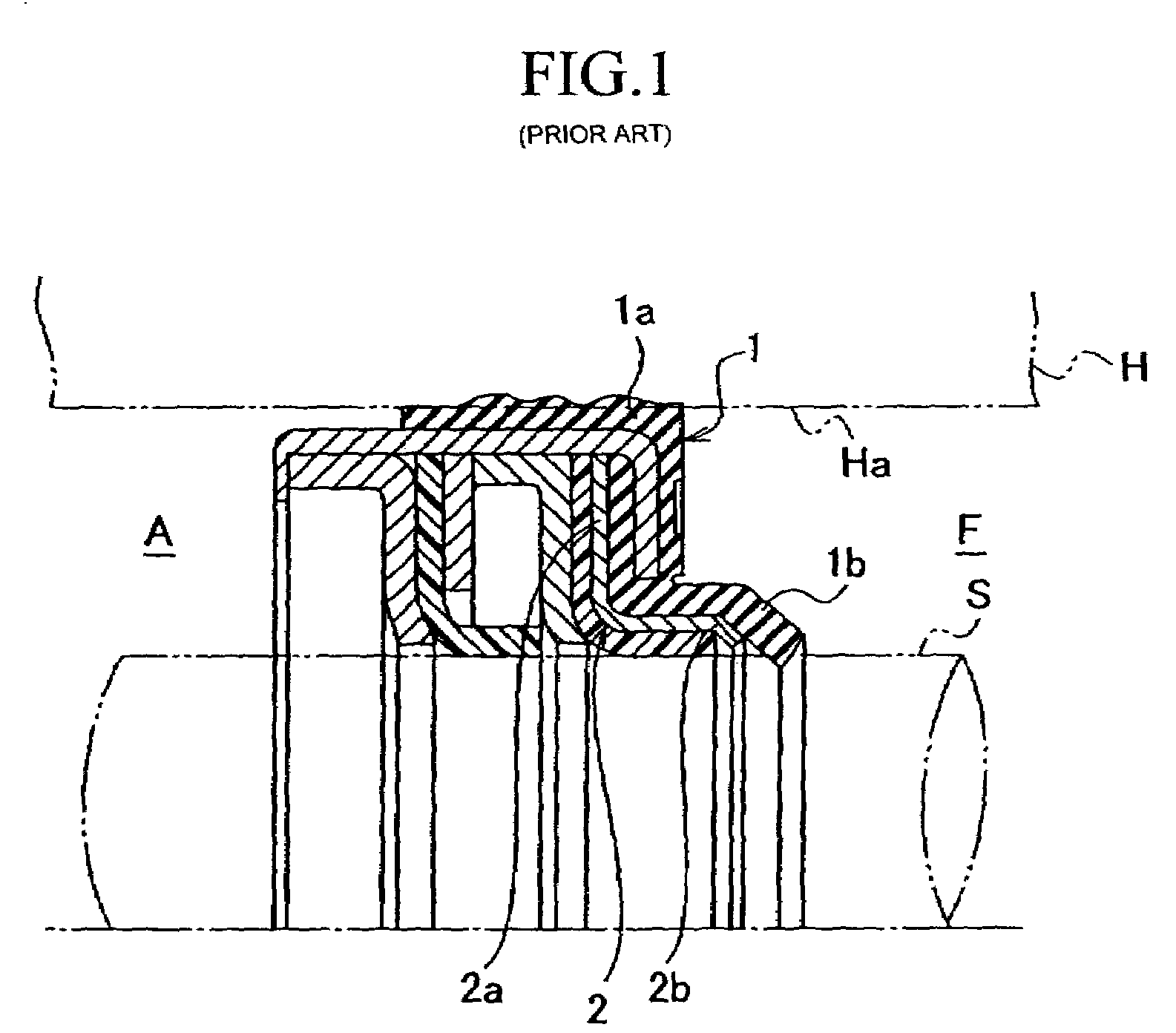
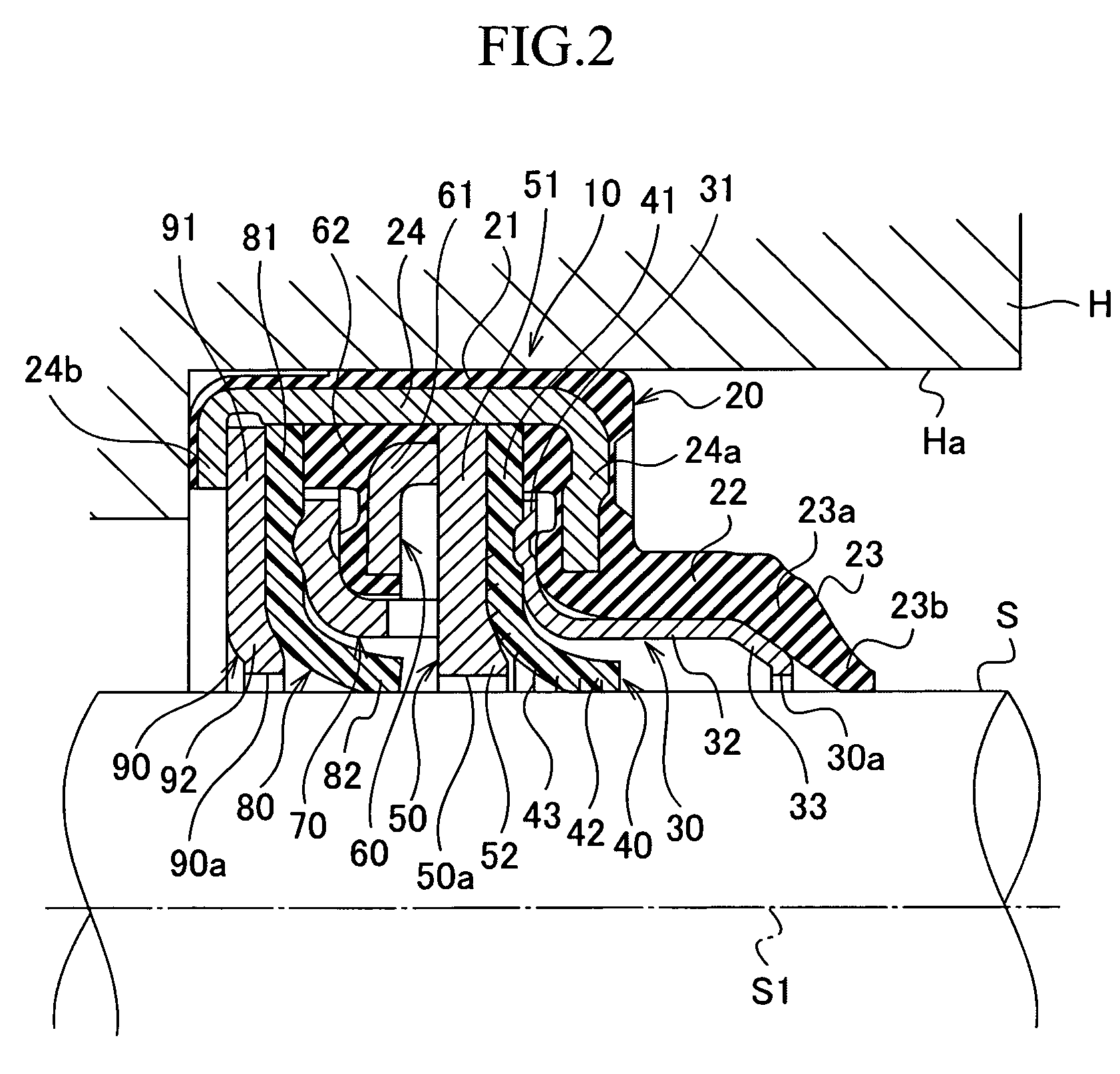
[0032]The compressor has a housing H that defines an outline and a rotational shaft S that transmits a rotational driving force to a compression mechanism contained in the housing H from outside. A lip-type seal 10 according to the present invention is attached so as to seal a space between the rotational shaft S (more specifically, an outer circumferential surface of the rotational shaft S) and the housing H (more specifically, an inner wall surface of a hole of the housing H), whereby an internal space (fluid) F is blocked from atmosphere A.

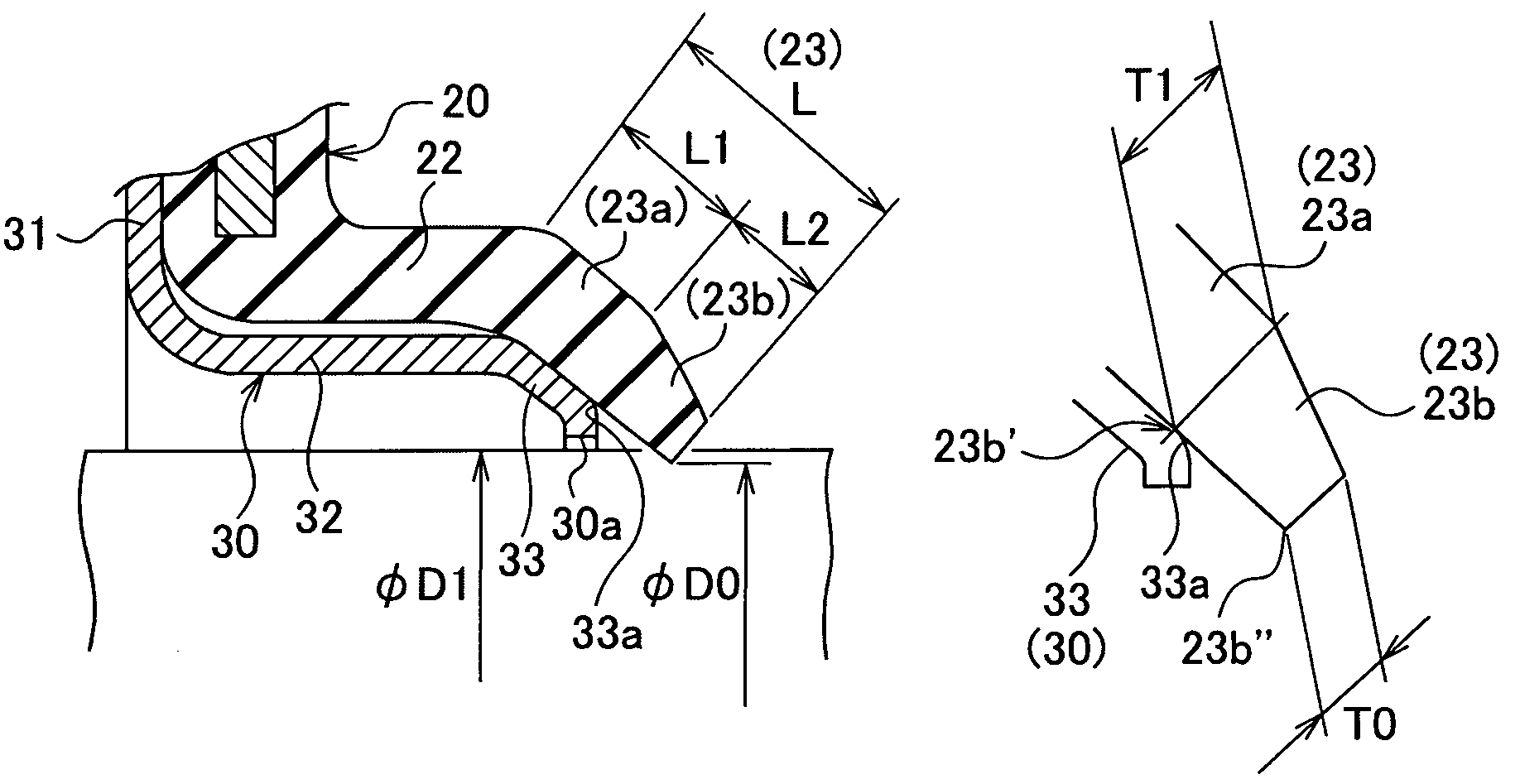
[0033]As shown in FIG. 2 and FIG. 3, the lip-type seal 10 includes a seal ring 20 that defines an out...


PUM


Abstract

The lip-type seal of the present invention includes a seal ring made of an elastic material so as to have an annular fitted part that is fitted to a housing and a lip part that extends from the fitted part inwardly in a radial direction in the shape of a substantially conical ring and that is brought into contact with a shaft, and a support ring including an annular joint part joined to the fitted part and an annular supporting part that defines a hole through which the shaft passes, that extends from a side of the joint part to a halfway area of the lip part, and that supports the lip part from inside in a radial direction. The lip part is tapered in cross section from an area from which non-contact with the supporting part starts toward an end thereof.

Description

TECHNICAL FIELD[0001]The present invention relates to a lip-type seal for withstanding pressure, and, more particularly, to a lip-type seal with which a space between a housing and a rotational shaft of an air conditioning compressor used in an air conditioning system of, for example, a vehicle is sealed.BACKGROUND ART[0002]In a conventional compressor mounted on, for example, a vehicle, in order to seal a periphery of a rotational shaft protruding from its housing outwardly, a lip-type seal is fitted between the housing and the rotational shaft so as to isolate an internal space (fluid) F in the housing from atmosphere A.[0003]An example of such a known lip-type seal is shown in FIG. 1. This lip-type seal is made up of a seal ring 1 and a support ring 2. The seal ring 1 is made of an elastic material like rubber so as to define a fitted part 1a fitted to a hole Ha of a housing H, and a lip part 1b conically extending from the fitted part la inwardly in a radial direction. The suppo...

Claims


Application Information

Patent Timeline
Patent Type & Authority Patents(United States)
IPC IPC(8): F16J15/32F16J15/3252
CPCF16J15/3216F16J15/3228F16J15/16F16J15/32
Inventor OIYAMA, KOICHIROIKEDA, YASUHIROICHIYASU, HAJIMEMIYAI, ICHIROYAMADA, TAKESHIOSAKO, MASAMI
Owner EAGLE INDS
Why Eureka
Try Eureka