Ratchet type tensioner

a ratchet tensioner and ratchet mechanism technology, applied in mechanical equipment, belts/chains/gearings, etc., can solve the problems of reducing the size of the end of the piston, and reducing the radial dimension of the portion, so as to reduce the size of the piston end and the effect of miniaturizing the tensioner

Active Publication Date: 2008-12-23
TSUBAKIMOTO CHAIN CO
View PDF17 Cites 9 Cited by
  • Summary
  • Abstract
  • Description
  • Claims
  • Application Information

AI Technical Summary

Benefits of technology

[0009]An object of the invention is to provide a ratchet tensioner in which the loss and buckling of the ratchet-biasing spring are prevented, so that the tensioner can operate reliably for an extended period of time.
[0013]The presence of the piston slidable in the spring-accommodating hole in the tensioner housing ensures that the pawl biasing spring operates without being exposed outside the hole. Consequently, the pawl-biasing spring cannot buckle or drop out of the spring-accommodating hole, and can exert a pivoting force on the pawl smoothly over a long period of time. In addition, the reduction of the size of the end of the piston that contacts the pawl makes it possible to miniaturize the tensioner by making the portion of the pawl on the side of the pawl pivoting shaft opposite from the pawl teeth shorter, while avoiding excessive reduction in the radial dimensions of the portion of the pawl surrounding the pivoting shaft.
[0014]Furthermore, when the front of the piston is flat, and the part of the pawl that is contacted by the piston has a convexly curved surface, the force exerted by the pawl on the piston is always oriented along the direction of the center line of the pawl-biasing spring. The avoidance of transverse force components ensures smooth and reliable operation of the ratchet mechanism as the pawl is rotated by protruding and retracting movement of the plunger during operation of the tensioner.

Problems solved by technology

As the chain elongates over time, due to mechanical wear, the ratchet allows the plunger to protrude, thereby taking up the slack resulting from elongation of the chain, and maintaining proper chain tension over a long time.
Repeatedly buckling of the spring compromises its elasticity, and can result in failure of the ratchet mechanism.
These minimum size requirements present obstacles to miniaturization of the tensioner.

Method used


Image

  • Ratchet type tensioner
  • Ratchet type tensioner
  • Ratchet type tensioner

Examples


Embodiment Construction

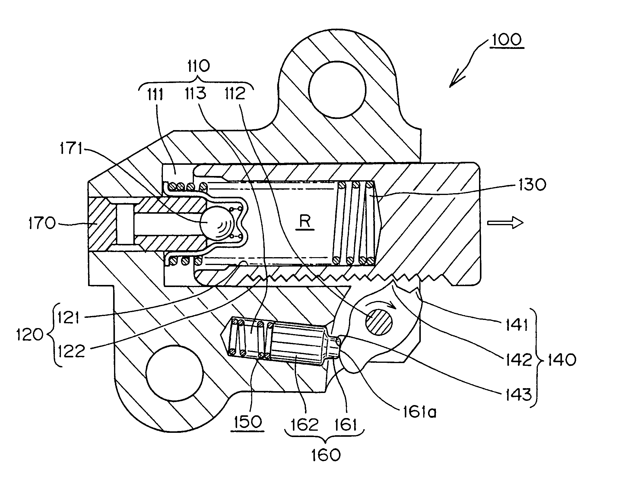
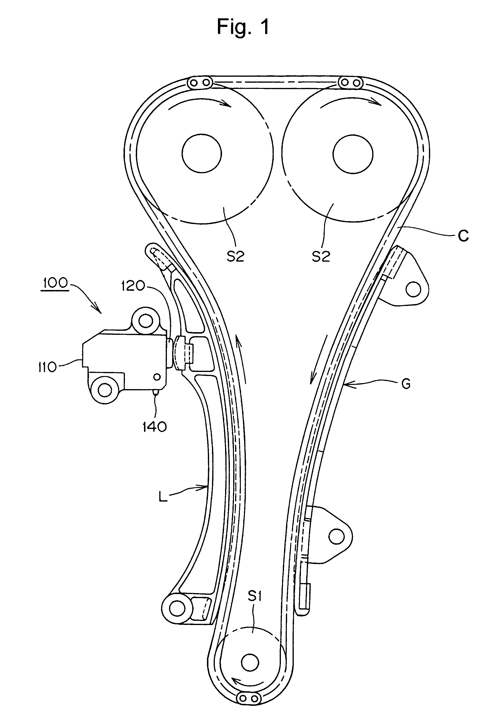
[0023]As shown in FIG. 1, the ratchet tensioner 100, in accordance with the invention, is mounted adjacent the slack side of a timing chain C, which transmits rotation from a crankshaft sprocket S1 to a pair of camshaft sprockets S2. The plunger 120 of the tensioner is slidable in the tensioner housing 110, and protrudes therefrom, pressing against the back of a pivoted lever L at a location spaced from the lever's pivot axis. The lever L includes a sliding contact shoe, on which the slack side of the chain slides. A fixed guide G, guides the tension side of the timing chain C. The tensioner, the lever L, and the guide G may all be mounted on the engine block (not shown). Arrows indicate the direction of rotation of the sprockets, and the direction of movement of the chain C.

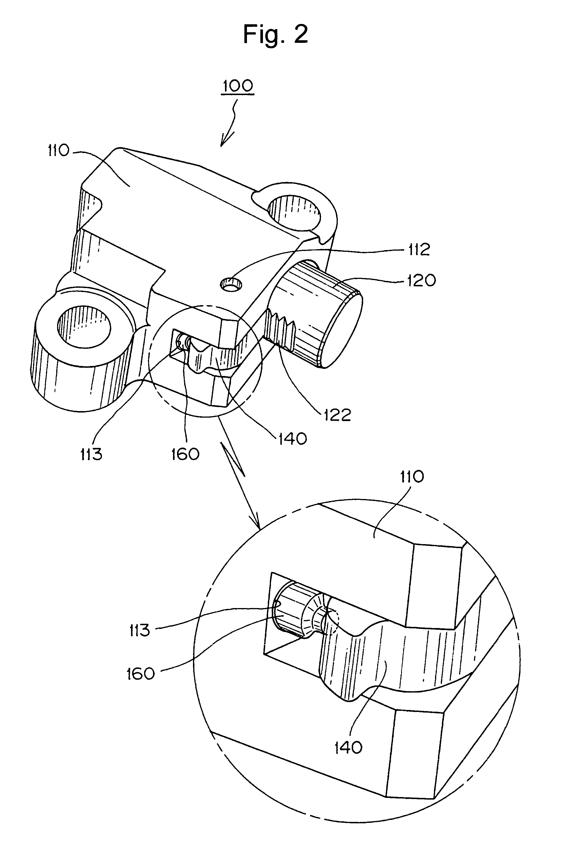
[0024]As shown in FIGS. 2, 3 and 4, the plunger 120 fits slidably in a plunger-accommodating hole 111 in the tensioner housing 110. The plunger is hollow, having a blind bore 121, with an opening facing the bott...


PUM


Abstract

In a ratchet tensioner, a pawl, pivoted on a shaft in the tensioner housing, engages teeth on a plunger protruding from the housing to allow protruding movement of the plunger, while limiting retracting movement to a backlash distance. The pawl is biased into contact with the teeth on the plunger by a spring disposed in a hole in the housing and acting, through a piston slidable in the same hole, against a convexly curved surface of the pawl. The piston has a reduced portion in engagement with the pawl, which allows the pawl to be miniaturized without excessively reducing the radial dimensions of the portion of the pawl surrounding the pivot shaft.

Description

CROSS-REFERENCE TO RELATED APPLICATIONS[0001]This application claims priority on the basis of Japanese Patent Application 2005-050790, filed on Feb. 25, 2005. The disclosure of Japanese Patent Application 2005-050790 is hereby incorporated by reference.FIELD OF THE INVENTION[0002]The invention relates to improvements in a ratchet tensioner used for applying proper tension to a flexible, endless, traveling, transmission medium such as the timing chain, timing belt, or the like, in the internal combustion engine of a vehicle.BACKGROUND OF THE INVENTION[0003]In timing transmissions of the kind in which a chain is used to transmits power from a crankshaft to one or more camshafts of an engine, ratchet tensioners have been widely used for maintaining proper tension in the slack side of the timing chain. The tensioner typically presses against a pivoted tensioner lever, on which the chain slides, and the pivoted lever, in turn, presses against the chain, suppressing vibration.[0004]A conv...

Claims


Application Information

Patent Timeline
Patent Type & Authority Patents(United States)
IPC IPC(8): F16H7/08
CPCF16H7/0836F16H7/0848F16H2007/0806F16H2007/0853F16H2007/0859
Inventor HAYAMI, ATSUSHISATO, TOSHIFUMI
Owner TSUBAKIMOTO CHAIN CO
Why Eureka
Try Eureka