
Injection catheter with controllably extendable injection needle

a catheter and controllable technology, applied in the field of catheters with injection needles, can solve the problems of difficult activity of positioning and monitoring the position of the distal tip of the catheter, or the infusion needle, and achieve the effect of precise location information

Inactive Publication Date: 2008-12-23
BIOSENSE WEBSTER INC
View PDF57 Cites 67 Cited by
  • Summary
  • Abstract
  • Description
  • Claims
  • Application Information

AI Technical Summary

Benefits of technology

[0010]Copending U.S. patent application Ser. No. 09/019,453, entitled “Intracardiac Drug Delivery,” assigned to an affiliated company of the assignee of this application, discloses an injection catheter system for infusing a diagnostic or therapeutic agent into the wall of an organ which

Problems solved by technology

Targeted delivery of therapeutic or diagnostic agents, such as occurs in gene therapy, is very desirable but often presents a difficult challenge.
There are several problems to his procedure which must be overcome in order to obtain satisfactory results from such therapy, such as the problems of obtaining access to the delivery site, transporting the therapeutic agent to the desired site, injecting the therapeutic agent at the proper depth within the organ tissue, steering the distal end of the catheter to a desired location within the organ prior to infusing the agent, and positioning the distal tip of the catheter at precisely the same location where prior measurements have indicated that the drug should be infused.
In the case of an organ, such as the heart, in which the walls are in constant motion, the activity of positioning and monitoring the position of the distal tip of the catheter, or infusion needle, becomes especially difficult.

Method used


Image

  • Injection catheter with controllably extendable injection needle
  • Injection catheter with controllably extendable injection needle
  • Injection catheter with controllably extendable injection needle

Examples


Embodiment Construction

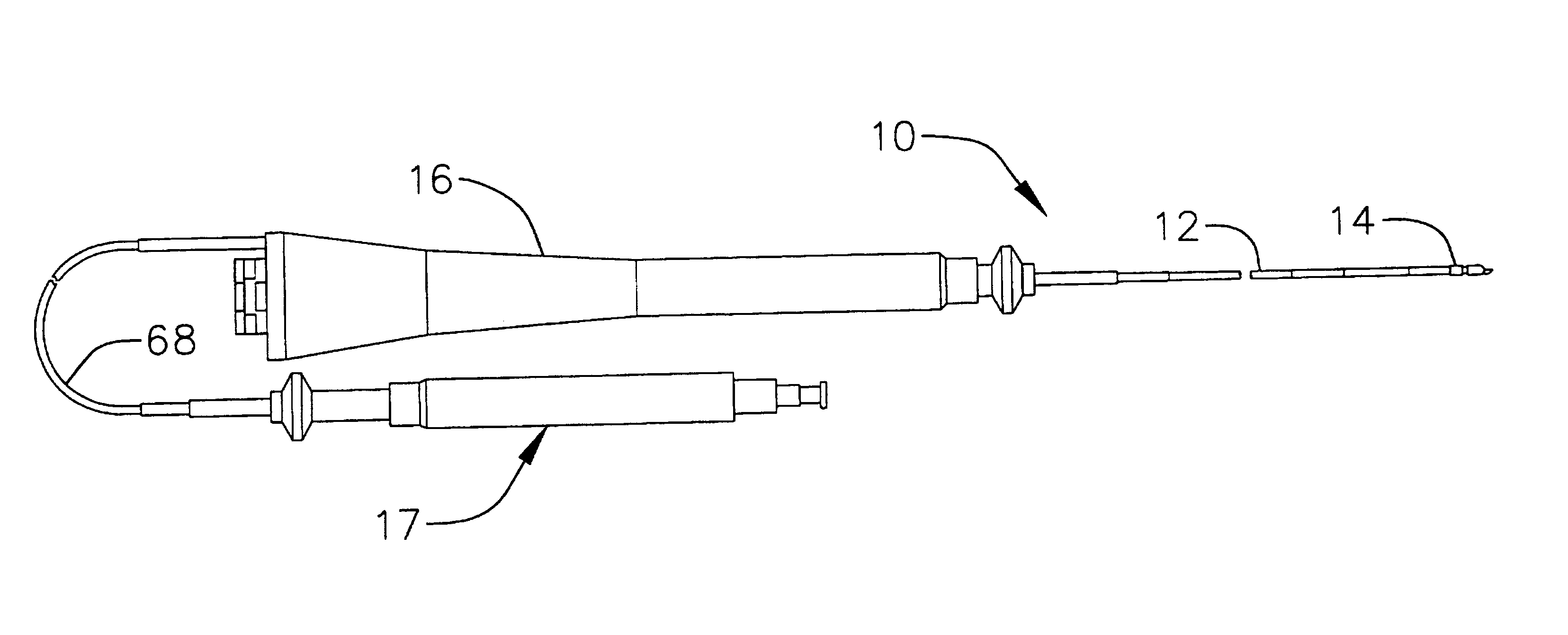
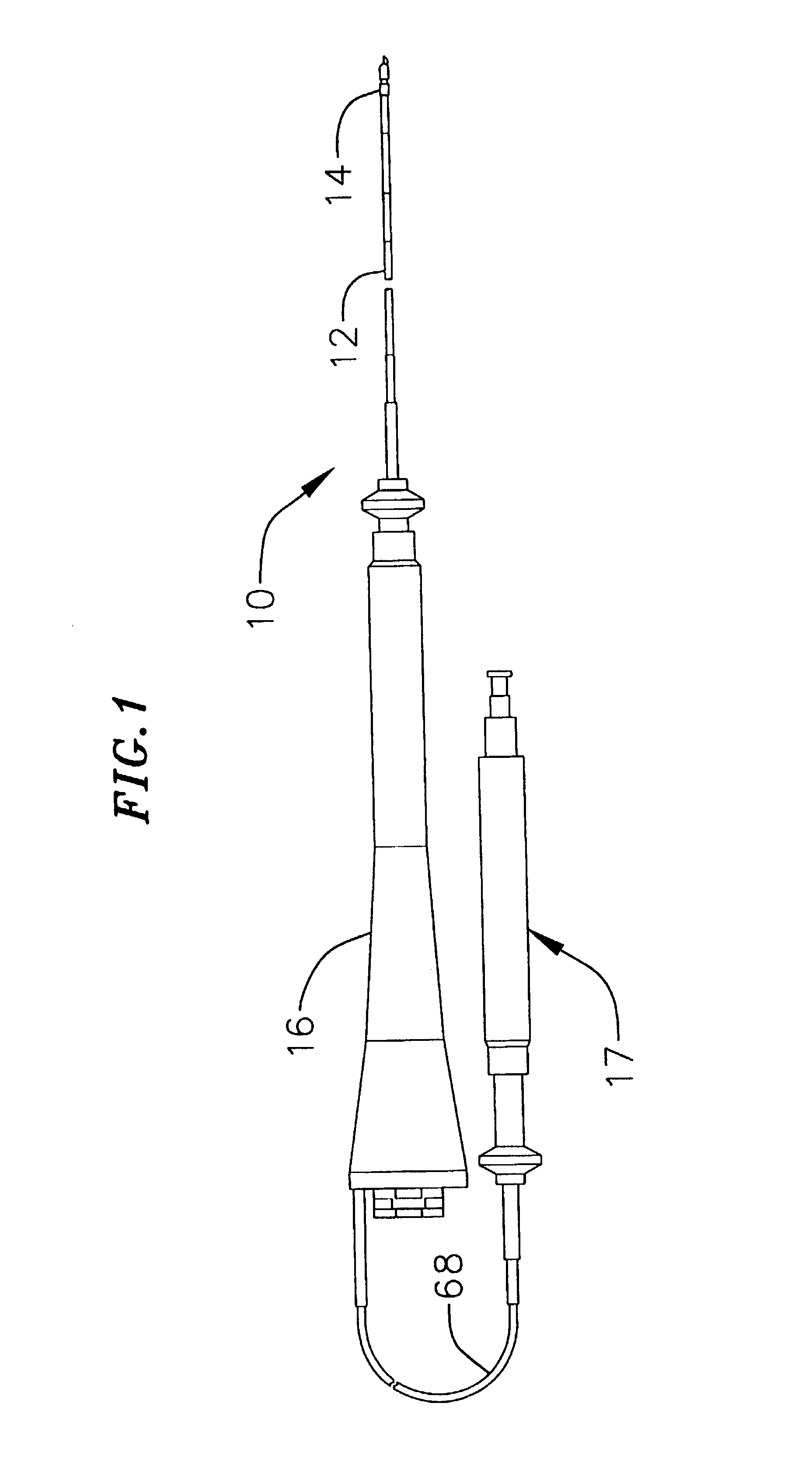
[0022]In a preferred embodiment of the invention, there is provided a catheter for use for injection of a therapeutic or diagnostic agent into the heart. As shown in FIG. 1, catheter 10 comprises an elongated catheter body 12 having proximal and distal ends, a tip section 14 at the distal end of the catheter body 12, a deflection control handle 16 at the proximal end of the catheter body 12, and a needle control handle 17 attached indirectly to the catheter body proximal the deflection control handle.

[0023]With reference to FIGS. 5 and 7, the catheter body 12 comprises a single, central or axial lumen 18. The catheter body 12 is flexible, i.e., bendable, but substantially non-compressible along its length. The catheter body 12 may be of any suitable construction and made of any suitable material. A presently preferred construction comprises an outer wall 22 made of a polyurethane or nylon. The outer wall 22 comprises an imbedded braided mesh of stainless steel or the like to increas...


PUM


Abstract

An injection catheter is provided. The injection catheter comprises a catheter body comprising a flexible tubing having proximal and distal ends and at least one lumen therethrough. A needle control handle is provided at the proximal end of the catheter body. The needle control handle comprises an outer body having a piston chamber therein, a piston slidably mounted within the piston chamber; and a compression spring in the piston chamber between the outer body and the piston. An injection needle extends through the catheter body and at least a portion of the needle control handle. The injection needle has a proximal end attached to one of the outer body and the piston and a distal end within the catheter body. Longitudinal movement of one of the outer body and the piston relative to the other of the outer body and the piston compresses the compression spring and moves the injection needle distally relative to the catheter body so that the distal end of the injection needle extends outside the distal end of the catheter body.

Description

CROSS-REFERENCE TO RELATED APPLICATION[0001]This application is a continuation of U.S. application Ser. No. 09 / 709,686, filed Nov. 9, 2000, now U.S. Pat. No. 6,540,725, which claims the benefit of U.S. Provisional Application No. 60 / 165,354, filed Nov. 12, 1999, and is a continuation-in-part of U.S. patent application Ser. No. 09 / 280,202, filed Mar. 29, 1999, now U.S. Pat. No. 6,165,164, which claims the benefit of U.S. Provisional Patent Application Nos. 60 / 088,019, filed on Jun. 4, 1998, and 60 / 088,984, filed on Jun. 11, 1998, the entire disclosures of which are incorporated herein by reference.FIELD OF THE INVENTION[0002]This invention relates to a catheter with an injection needle for infusing therapeutic or diagnostic agents into the tissue of organs, and more particularly to a catheter having a springloaded handle for controlled extension of an injection needle.BACKGROUND OF THE INVENTION[0003]Targeted delivery of therapeutic or diagnostic agents, such as occurs in gene therap...

Claims


Application Information

Patent Timeline
IPC IPC(8): A61M25/01A61B18/14A61B18/24A61M25/00
CPCA61B18/1492A61B18/24A61M25/0069A61M25/008A61M25/0084A61M25/0082A61M25/0147A61M2025/0089A61M2025/0091A61M2025/015
Inventor PONZI, DEAN M.
Owner BIOSENSE WEBSTER INC
Features
  • Generate Ideas
  • Intellectual Property
  • Life Sciences
  • Materials
  • Tech Scout
  • Unparalleled Data Quality
  • Higher Quality Content
  • 60% Fewer Hallucinations
Learn More