Static anterior cervical plate

a technology of anterior cervical plate and plate, which is applied in the field of orthopedic surgery, can solve the problems of instability of bone or joint, and increased pain and danger, and achieve the effect of preventing dislocation of plate and preventing trauma to internal body tissu

Active Publication Date: 2008-12-23
ATLAS SPINE
View PDF128 Cites 32 Cited by
  • Summary
  • Abstract
  • Description
  • Claims
  • Application Information

AI Technical Summary

Benefits of technology

[0012]Disclosed is a bone plate for use in anterior cervical spinal fixation. The bone plate has interlocking components to prevent dislodgement of the plate due to anatomical forces. The bone plate is C-shaped with a smooth exposed surface to prevent trauma to internal body tissue. The plate spans the intervertebral space with each end attached to an adjacent vertebrae by bone screws threadably engaged with tubular bone anchors. The plate has a screw lock in each end for preventing the bone screws from backing out.
[0013]It is an objective of this invention to provide a bone plate, suitable for anterior cervical fixation, having countersunk screw holes, a low profile in cross section allowing the bone plate to be countersunk into the bone and a smooth distal surface to reduce the possibility of traumatizing adjacent soft tissue during use.
[0014]Another objective of this invention is to provide a reduced width in the central portion of the bone plate for visualizing the intervertebral space below the proximal surface of the plate.

Problems solved by technology

The interface between the bone screws and the bone presents problems of stability and long term usage that have been addressed in different ways.
Severe back-out results in the bone screw working itself out of the bone and / or plate resulting in instability of the bone or joint.
This situation results in increasing pain and danger from the instability, as well as, the movement of the screw.
There may be several reasons for the back-out but anatomical stresses from body movements contributes greatly to the problem.
Such devices are not particularly suited for deployment on the anterior aspect of the spine because of the close proximity of vital soft tissue organs which dictate a smooth, low profile, contoured surface.

Method used


Image

  • Static anterior cervical plate
  • Static anterior cervical plate
  • Static anterior cervical plate

Examples


Embodiment Construction

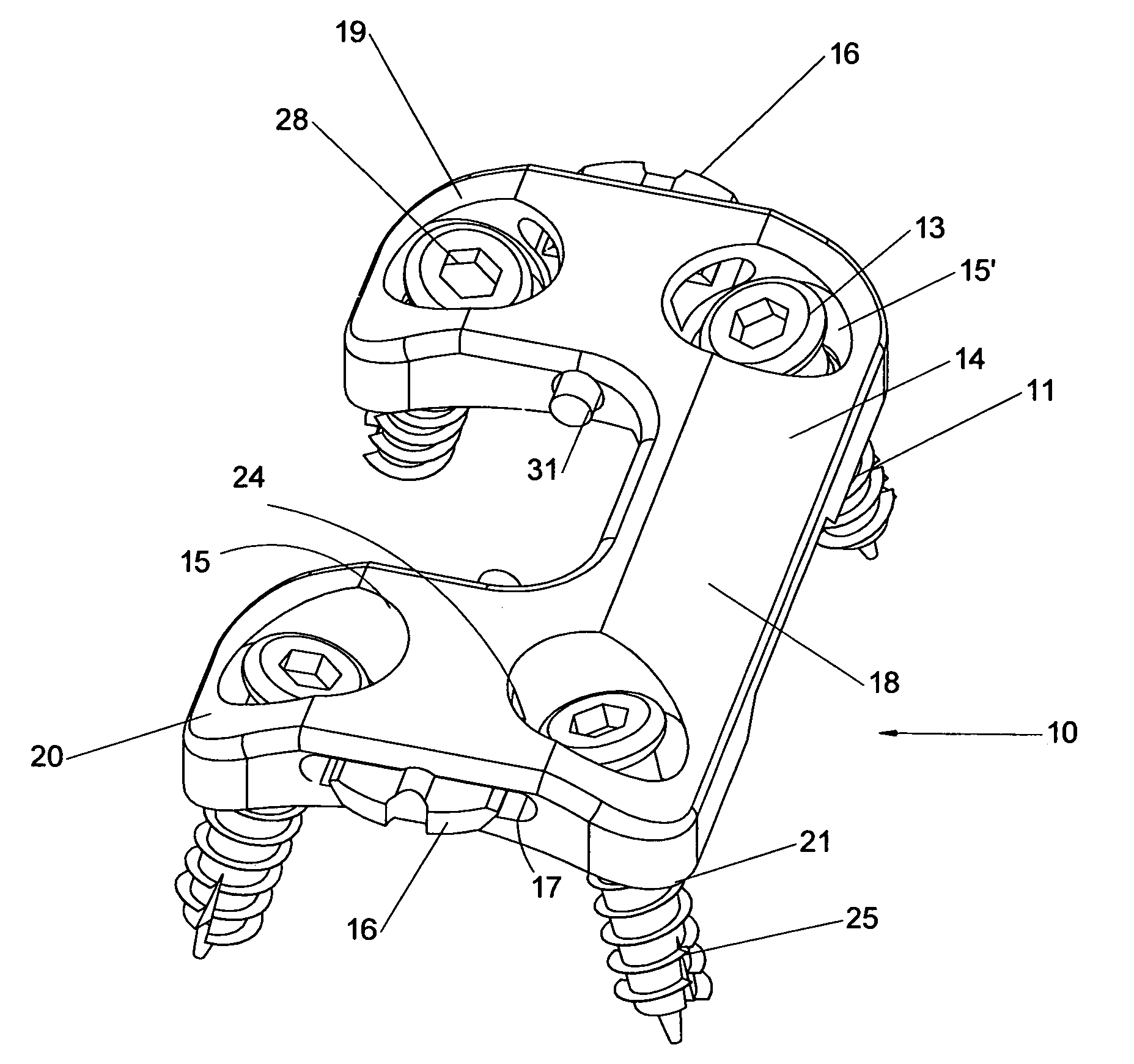
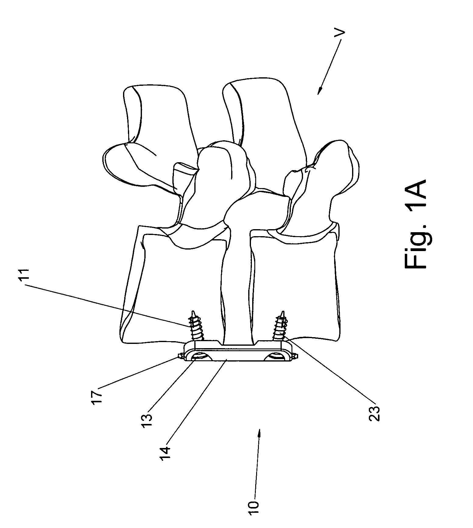
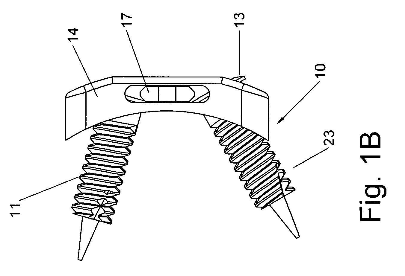
[0024]The bone plate system 10 may be made from any materials having requisite strength and being suitable for use in the body. One complete bone plate system is shown in FIG. 1 and FIG. 2 though it is understood that several different sizes of interchangeable components may be supplied together as a kit for mixing and matching components to size a system for a particular patient. A kit may have several different sized bone screws 11 varying in diameter and length. The different sized locking screws may have the same sized heads 13 to be used in different sized bone plates 14 with screw holes and larger countersunk depressions 15 of a complementary size. There may be several different sized screw locks 16 to fit into the different sized screw lock slots 17. The kit merely refers to the dissembled components that can be assembled to produce an integral whole which corresponds to the anatomical features of a particular patient.

[0025]The bone plate 14 is shaped in the form of a block l...


PUM


Abstract

A bone plate for use in anterior cervical spinal fixation has interlocking components to prevent dislodgement of the plate due to anatomical forces. The plate is formed in the shape of a block letter C and the exposed surface is smooth to prevent trauma to internal body tissue. The plate spans the intervertebral space with each end attached to an adjacent vertebrae by bone screws threadably engaged with the bone. The distal ends of the bone screws The plate has a screw lock in each end for preventing the locking screws from backing out.

Description

FIELD OF THE INVENTION[0001]This invention relates to the field of orthopedic surgery and, more particularly, to spinal fixation.BACKGROUND OF THE INVENTION[0002]The use of bone pins and plates for reducing fractures is well known in orthopedic medicine. The pins and plates extend across discontinuities in a bone to fix the broken ends in relation to each other to reduce pain and promote rapid healing without deformity. These devices are secured to the bone by bone screws or nails driven into the bone. More recently, pins, rods, plates and cages have been used to stabilize bone and joints that have deteriorated naturally or as a result of prior trauma. The bone plate of this invention is useful in all these situations.[0003]The interface between the bone screws and the bone presents problems of stability and long term usage that have been addressed in different ways. One of the major problems is usually termed as back-out. This defines the condition in which the screws attaching the...

Claims


Application Information

Patent Timeline
Patent Type & Authority Patents(United States)
IPC IPC(8): A61B17/80A61B17/70A61B17/86
CPCA61B17/7059A61B17/8042A61B17/8635
Inventor BAYNHAM, BRET O.BAYNHAM, G. CLAYBAYNHAM, MATTHEW G.CAMPBELL, DAVID R.
Owner ATLAS SPINE
Why Eureka
Try Eureka