Patellar retractor and method of surgical procedure on knee

a technology which is applied in the field of patellar retraction and surgical procedure on knee, can solve the problems of long and deep incisions, ineffective practice of patellar retraction, and risk of damage to the tendon and/or the patella, so as to achieve efficient recline of the quadriceps muscle tendon and sufficient lateral disengagement of the patella. , the effect of simple manufacture and us

Inactive Publication Date: 2008-12-23
CORIN
View PDF61 Cites 44 Cited by
  • Summary
  • Abstract
  • Description
  • Claims
  • Application Information

AI Technical Summary

Benefits of technology

[0008]The structure of the retractor according to the invention is particularly simple to manufacture and to use. When the surgeon seeks access to one of the femoral condyles, in particular to implant at that level a unicompartmental prosthesis, he inserts the distal end part of the retractor in the femoral intercondylar space, then, by causing each tip to abut on the wall of the treated condyle facing the intercondylar space, he makes a lever with the body of the retractor in order, using the lateral wing, to dislocate the patella by pushing it in a medial-lateral direction directed towards the other condyle. This simple gesture allows the surgeon to recline the quadriceps muscle tendon efficiently, by stressing the latter at the level of its current part, i.e. its part containing the patella, and using the lateral wing from which the frontal surface extends along the current part of the tendon. It will be understood that, in the invention, the term “tip” is understood broadly as a swelling or an element in relief, able to allow a stable abutment of the distal end of the retractor in the intercondylar space during its stress as lever for thrusting the patella.
[0009]As the stress of the quadriceps muscle tendon is applied over a substantial length of the current part of the tendon, no traumatic excess pressure or strain is applied to the tendon, while guaranteeing a sufficient lateral disengagement of the patella without having to turn it completely on itself. During the subsequent steps of the surgical procedure, particularly during osseous cuts of the condyle to be treated, the lateral wing of the retractor efficiently holds the patella in its reclined position while protecting it from the ancillary instruments used at the level of the treated condyle, for example cutting tools, since the wing is in that case interposed in the medial-lateral direction between the front zone of the treated condyle and the current part of the quadriceps muscle tendon. As the patellar retractor is advantageously manipulated in one hand, the operating gesture is simple and easily reproducible.
[0021]The invention also proposes a method of surgical procedure on the knee which allows the patella to be efficiently reclined without turning completely on itself in order to offer a wide field of vision for the operation, while limiting the extent and depth of the necessary incisions or the like, in particular which does not necessitate accessing the medullary cavity of the femur or of the tibia.

Problems solved by technology

Such patellar retractors prove in practice to be inefficient insofar as, by elasticity of the quadriceps muscle tendon, the patella tends to resume its initial place such that only a small extent of the lower zone of the tendon is efficiently disengaged towards one of the lateral sides of the knee.
The surgeon is in that case often obliged to use these patellar retractors to force on the quadriceps muscle tendon and completely turn the patella round, risking damage to the tendon and / or the patella.
In addition, as these patellar retractors abut against the outer lateral face of the tibia, their use requires a long and deep incision of the soft parts of the knee, even if the purpose of the operation is to implant a unicompartmental prosthesis, i.e. a prosthesis to be implanted only on one of the external or internal sides of the knee.
Although, in practice this type of retractor limits the stress of the quadriceps muscle tendon and of the patella during reclination of the patella, the necessity of accessing the femoral medullar cavity leads to a long operation, which destroys the patient's osseous matter and is particularly invasive.

Method used


Image

  • Patellar retractor and method of surgical procedure on knee
  • Patellar retractor and method of surgical procedure on knee
  • Patellar retractor and method of surgical procedure on knee

Examples


Embodiment Construction

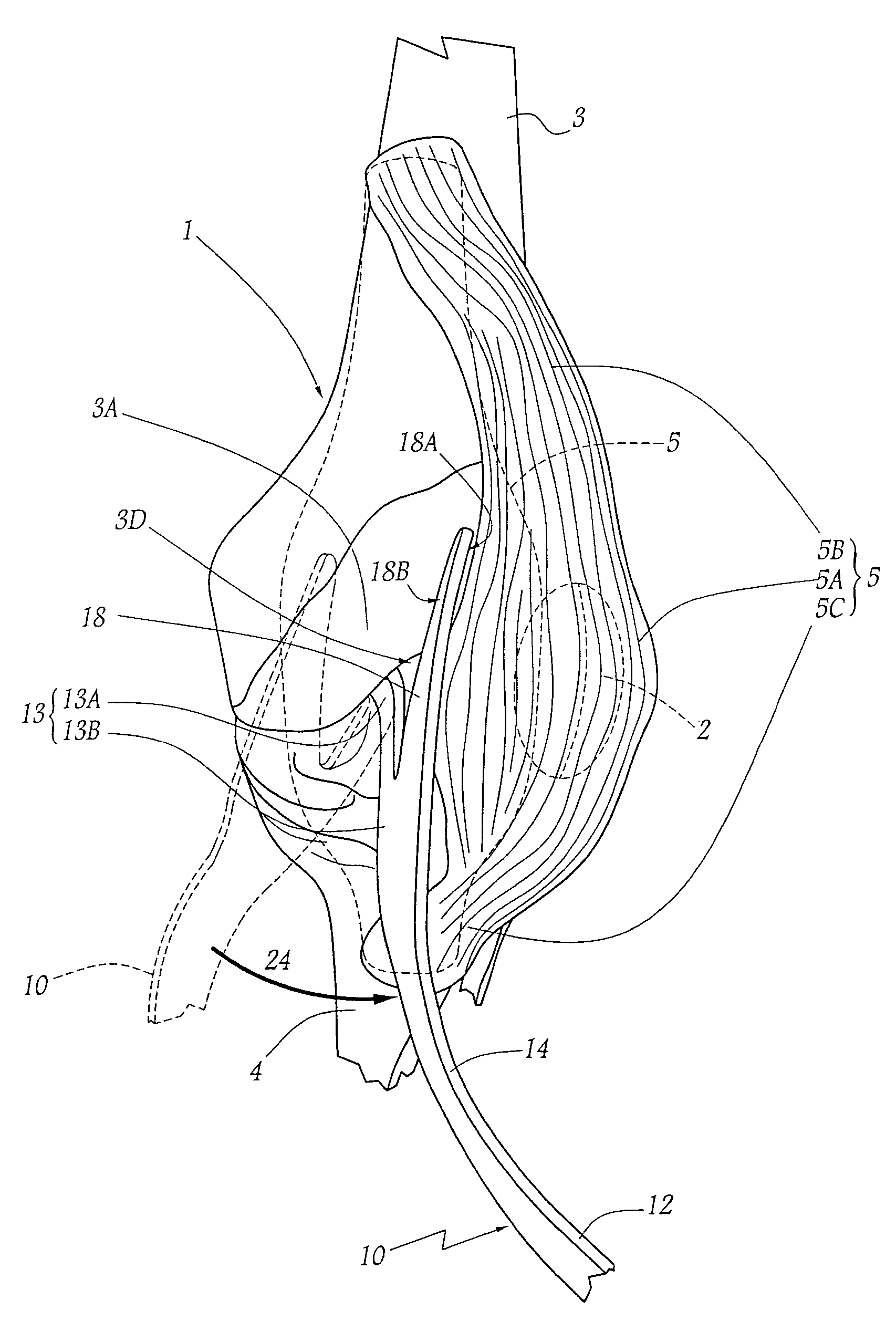
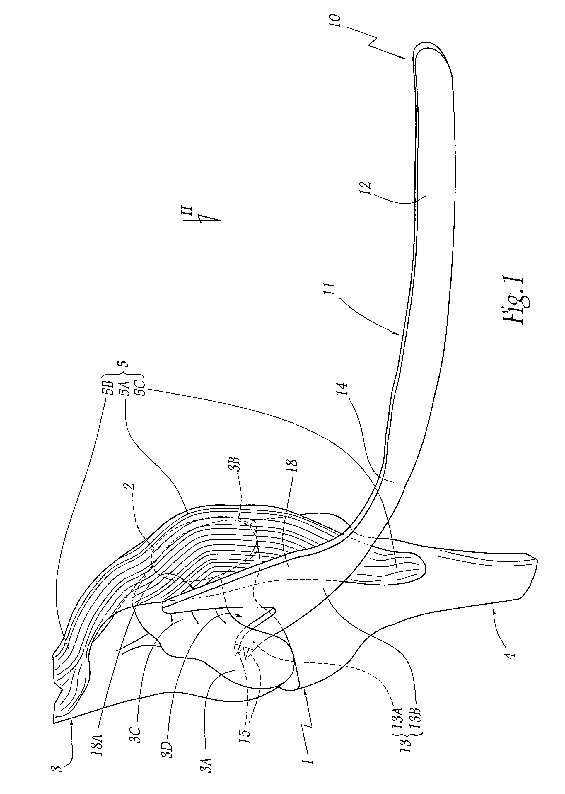
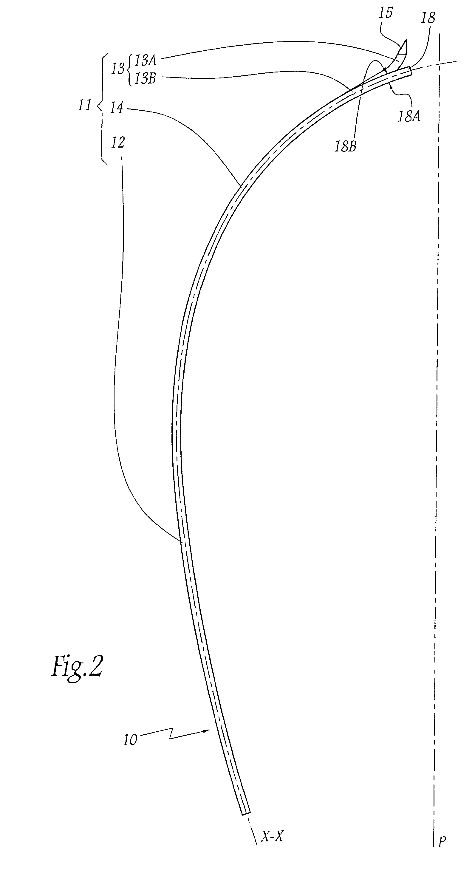
[0038]Referring now to the drawings, FIGS. 1 to 4 show a patellar retractor 10 adapted to recline the patella 2 of a knee 1. In FIGS. 1 and 4, the knee 1 is shown bent, with the lower epiphysis of the femur 3, the upper epiphysis of the tibia 4 and the tendon of the quadriceps muscle 5 which, to the rear of its current part 5A, contains the patella 2, while its upper (5B) and lower (5C) ends are respectively connected to the front faces of the femur 3 and of the tibia 4. The knee 1 shown being a right-hand knee, the femoral epiphysis includes an external condyle 3A and an internal condyle 3B, the upper parts of the condyles 3A and 3B being connected by an osseous trochlea 3C while, in their lower part, the condyles 3A and 3B are distant from each other in a medial-lateral direction, defining therebetween an intercondylar space 3D, clearly visible in FIG. 4. During the movements of the knee 1, the condyles 3A and 3B are articulated in complementary cavities 4A and 4B provided at the ...


PUM


Abstract

The distal end part of the retractor according to the invention is provided both with terminal tips for abutment on one of the femoral condylar walls which define therebetween the intercondylar space, and with a wing extending laterally in projection from this end part in order to form a frontal surface for thrust, in a medial-lateral direction, of that part of the quadriceps muscle tendon containing the patella when the tips are in abutment in the intercondylar space. By using this retractor as a lever, the wing efficiently reclines the patella, without turning it completely on itself, entirely exposing one of the femoral condyles. This invention is more particularly applicable to a surgical procedure for implanting a unicompartmental knee prosthesis.

Description

FIELD OF THE INVENTION[0001]The present invention relates to a patellar retractor intended to be used when performing knee surgery, particularly when a unicompartmental knee prosthesis is being implanted. The invention also relates to a method of surgical procedure on the knee employing such a retractor.BACKGROUND OF THE INVENTION[0002]When implanting a knee prosthesis, it is necessary to incise the anterior face of the knee and to recline the corresponding soft parts, i.e. disengage these soft parts rearwardly so as to render the operative field more visible and thus allow the surgeon to access the femoral and tibial epiphyses articulated on each other, particularly the femoral condyles and corresponding tibial articular cavities.[0003]U.S. Pat. No. 5,380,331 discloses using various retractors intended to facilitate access and treatment of osseous or ligamentary zones of the knee operated on, depending on the stage of operation underway. This type of retractor is in the form of an ...

Claims


Application Information

Patent Timeline
Patent Type & Authority Patents(United States)
IPC IPC(8): A61F2/38
CPCA61B17/02A61B17/025A61B2017/0268
Inventor ROCHETIN, OLIVIER
Owner CORIN
Why Eureka
Try Eureka