Reaction enhancing gas feed for injecting gas into a plasma chamber

a plasma chamber and gas feed technology, applied in plasma chambers, plasma techniques, coatings, etc., can solve the problems of low degree of dissociation of input gas, gas input configurations susceptible to wink out failures, and failures of plasma chambers, so as to reduce the speed of gas injection and reduce the speed of gas entering

Inactive Publication Date: 2008-12-23
ADVANCED ENERGY INDS
View PDF9 Cites 34 Cited by
  • Summary
  • Abstract
  • Description
  • Claims
  • Application Information

AI Technical Summary

Benefits of technology

[0005]In one aspect of the invention is a gas feed for injecting gas that reduces the speed at which the gas enters a chamber. The gas feed includes a gas inlet thr

Problems solved by technology

Specifically, plasma chambers may experience “plasma wink out” failures during operation.
Some of such failures can be attributed to the gas input configuration.
Specifically, some gas input configurations

Method used


Image

  • Reaction enhancing gas feed for injecting gas into a plasma chamber
  • Reaction enhancing gas feed for injecting gas into a plasma chamber
  • Reaction enhancing gas feed for injecting gas into a plasma chamber

Examples


first embodiment

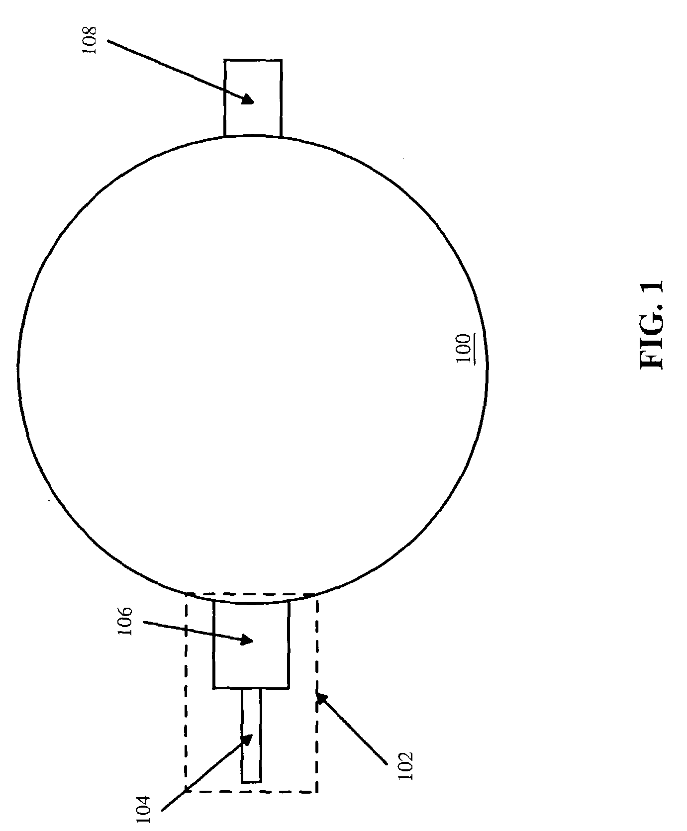
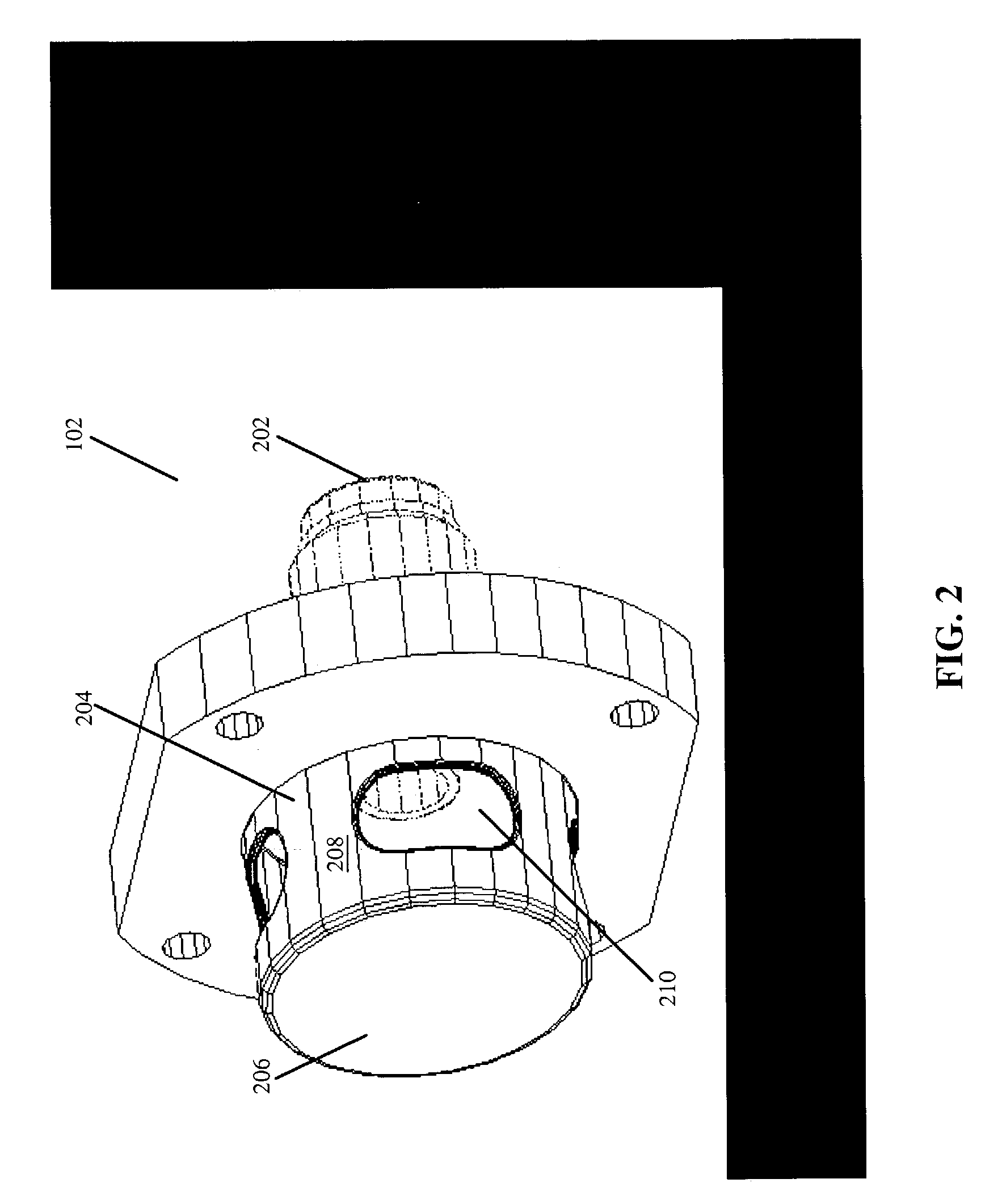
[0016]In a first embodiment, gas is diffused through at least one aperture located on the wall of a gas speed reducer. As illustrated in FIG. 2, the gas feed 102 comprises a gas inlet 202 through which gas is injected, a gas speed reducer 204 having an end wall 206, a side wall 208, and at least one aperture 210 located on the wall 208. As one of ordinary skill in the art would recognize, gas inlet 202 is a specific embodiment of gas inlet 104, and gas speed reducer 204 is a specific embodiment of gas speed reducer 106.

[0017]In this embodiment, gas is injected into the gas inlet 202 and goes through the gas speed reducer 204. Having a lower conductance than a direct injection gas feed, the gas speed reducer 204 introduces a pressure drop that decreases the speed at which the input gas interacts with the plasma. The gas exits the gas speed reducer 204 and enters the plasma chamber 100 through the one or more apertures 210 located on the wall 208. In this embodiment, the working gas e...

second embodiment

[0019]In a second embodiment, the gas feed 102 comprises a gas speed reducer, which is made of a channel such that, when traveling through any of the channels, the center of the input and output holes of the channel can only be connected by a broken line. FIGS. 3 and 4 show two examples of such embodiment. The gas speed reducer 300 (400) comprises a first section 302 (402), and a second section 304 (404) connected to the first section 302 (402).

[0020]As illustrated in FIG. 3, the first section 302 is attached to the second section 304 at a 90 degree angle. Of course, the angle of the attachment is not limited to 90 degrees. In FIG. 4, the second section 404 is an angled section (shown at 90 degrees, but not limited thereto), such that the second section creates two channels. It should be understood by one of ordinary skill in the art that one or both sections 302, 304, 402, 404 may each include a single channel (as in FIG. 3), or multiple channel channels (as in FIG. 4).

[0021]In thi...

third embodiment

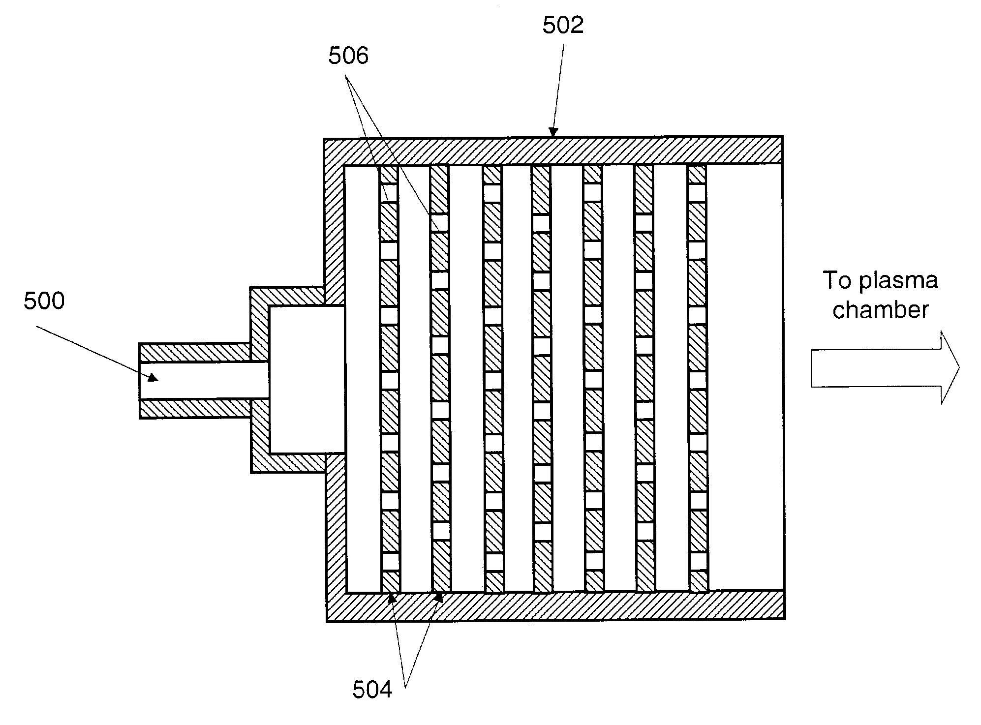
[0024]FIG. 5 shows an example of this invention. In this embodiment, the gas feed 102 comprises a gas speed reducer 502, which is made up of a stack of two or more perforated sheaths 504 arranged such that the holes 506 in consecutive sheaths are not aligned.

[0025]In this embodiment, gas is directly injected into the gas inlet 500. As the gas enters the gas speed reducer 502, it is forced to through a low conductance path formed by the stack of perforated sheaths 504. The gas then enters the plasma chamber 100 and interacts with the plasma discharge at a reduced speed.

3. General Matters

[0026]In the description above, for the purposes of explanation, numerous specific details are set forth in order to provide a thorough understanding of the present invention. It will be apparent, however, to one skilled in the art that the present invention may be practiced without some of these specific details. In other instances, well-known circuits, structures, devices, and techniques have been s...


PUM

PropertyMeasurementUnit
Angleaaaaaaaaaa
Speedaaaaaaaaaa

Abstract

In one aspect of the invention is a gas feed for injecting gas into a plasma-processing chamber that reduces the speed at which the gas interacts with the plasma discharge, so enhancing the stability of the plasma and the production of reaction products. In one embodiment, the gas feed comprises a gas speed reducer having apertures along its wall through which gas is distributed into the plasma chamber at a tangent to the chamber walls. In another embodiment, the gas feed comprises a gas speed reducer, which is made up of one or more channels such that, when traveling through the channels, the input and the output holes of the channels can only be connected by a broken line. In yet another embodiment, the gas speed reducer has a plurality of perforated sheaths, such that holes on one perforated sheath are not aligned with holes on another perforated sheath.

Description

BACKGROUND OF THE INVENTION[0001]1. Field[0002]Embodiments of this invention relate to the field of plasma chambers, and more specifically, to an apparatus for injecting gas into a plasma chamber that enhances the production of plasma reaction products.[0003]2. Description of the Related Art[0004]One of the areas in plasma processing that is commonly studied and troubleshooted is the topic of gas injection. Specifically, plasma chambers may experience “plasma wink out” failures during operation. Some of such failures can be attributed to the gas input configuration. Specifically, some gas input configurations are susceptible to wink out failures because they cause excessive perturbation of the plasma within the chamber. Also, some gas input configurations result in low degrees of dissociation of the input gas.SUMMARY OF THE INVENTION[0005]In one aspect of the invention is a gas feed for injecting gas that reduces the speed at which the gas enters a chamber. The gas feed includes a g...

Claims


Application Information

Patent Timeline
IPC IPC(8): B23K9/00H01J37/32H05H1/24
CPCH01J37/3244H05H1/24H01J37/32449
Inventor GONZALEZ, JUAN JOSESHABALIN, ANDREWTOMASEL, FERNANDO GUSTAVO
Owner ADVANCED ENERGY INDS
Why Eureka
Try Eureka