Load control structure for work vehicle
a technology for working vehicles and control structures, applied in the direction of fluid couplings, couplings, transportation and packaging, etc., can solve the problem of not providing a suitable structur
- Summary
- Abstract
- Description
- Claims
- Application Information
AI Technical Summary
Benefits of technology
Problems solved by technology
Method used
Image
Examples
case 4
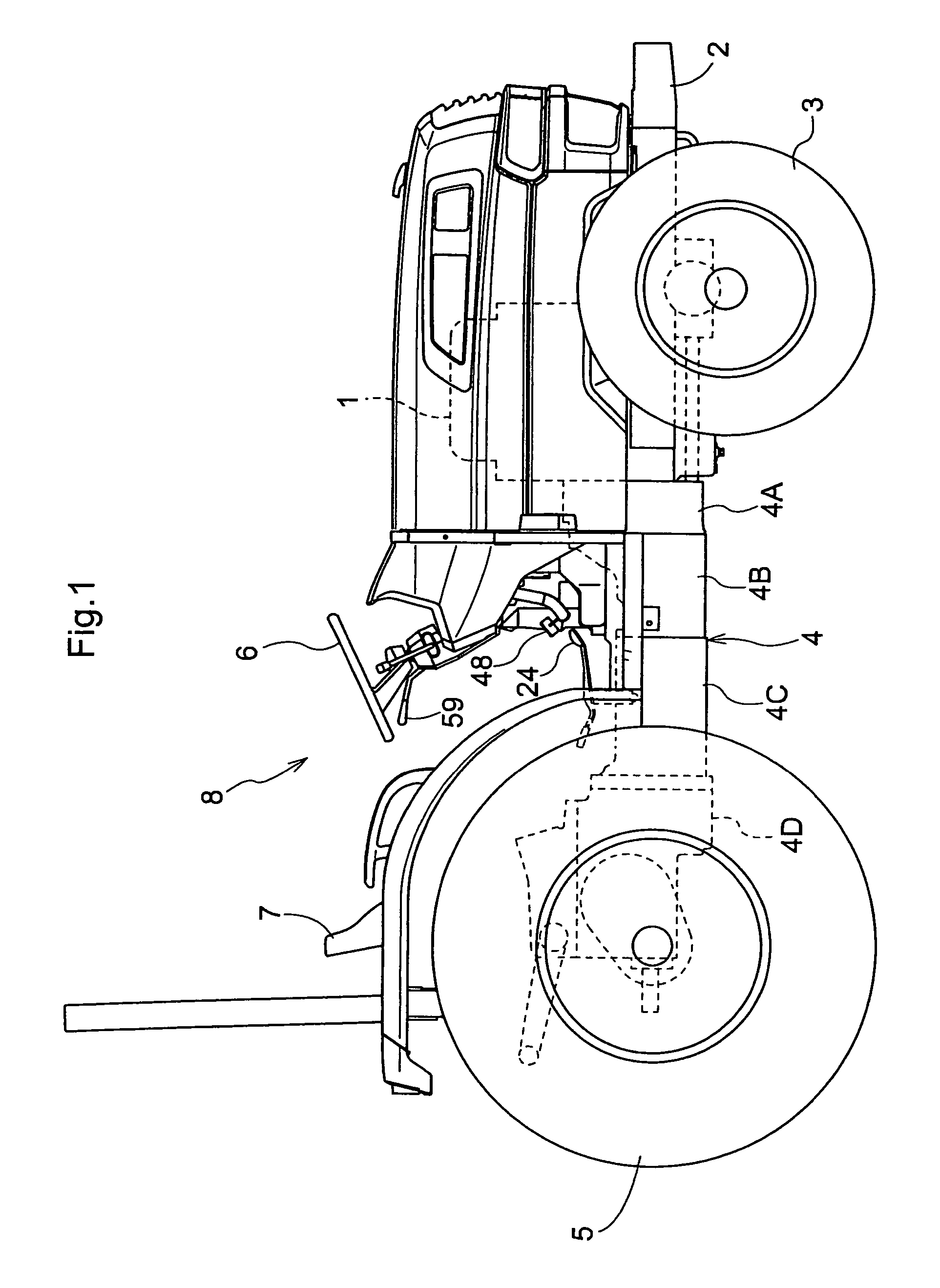
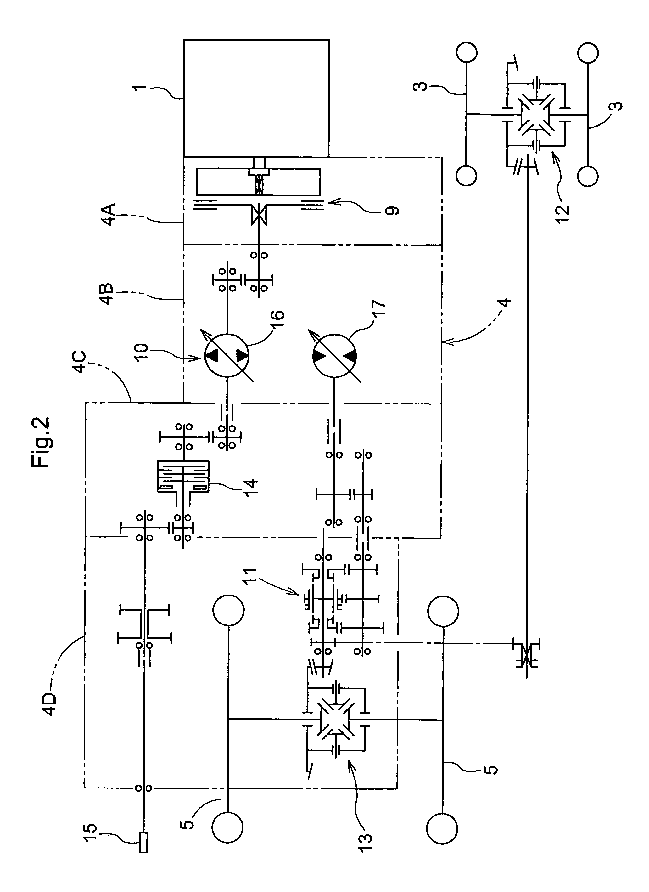
[0038]Transmission case 4 is formed by connecting the four casing parts: the first casing part 4A that houses the main clutch 9 etc., the second casing part 4B that houses hydrostatic type continuously variable speed change device 10 etc., the third casing part 4C that houses operation clutch 14 etc., and the fourth casing part 4D that houses gear type speed change device 11 etc.
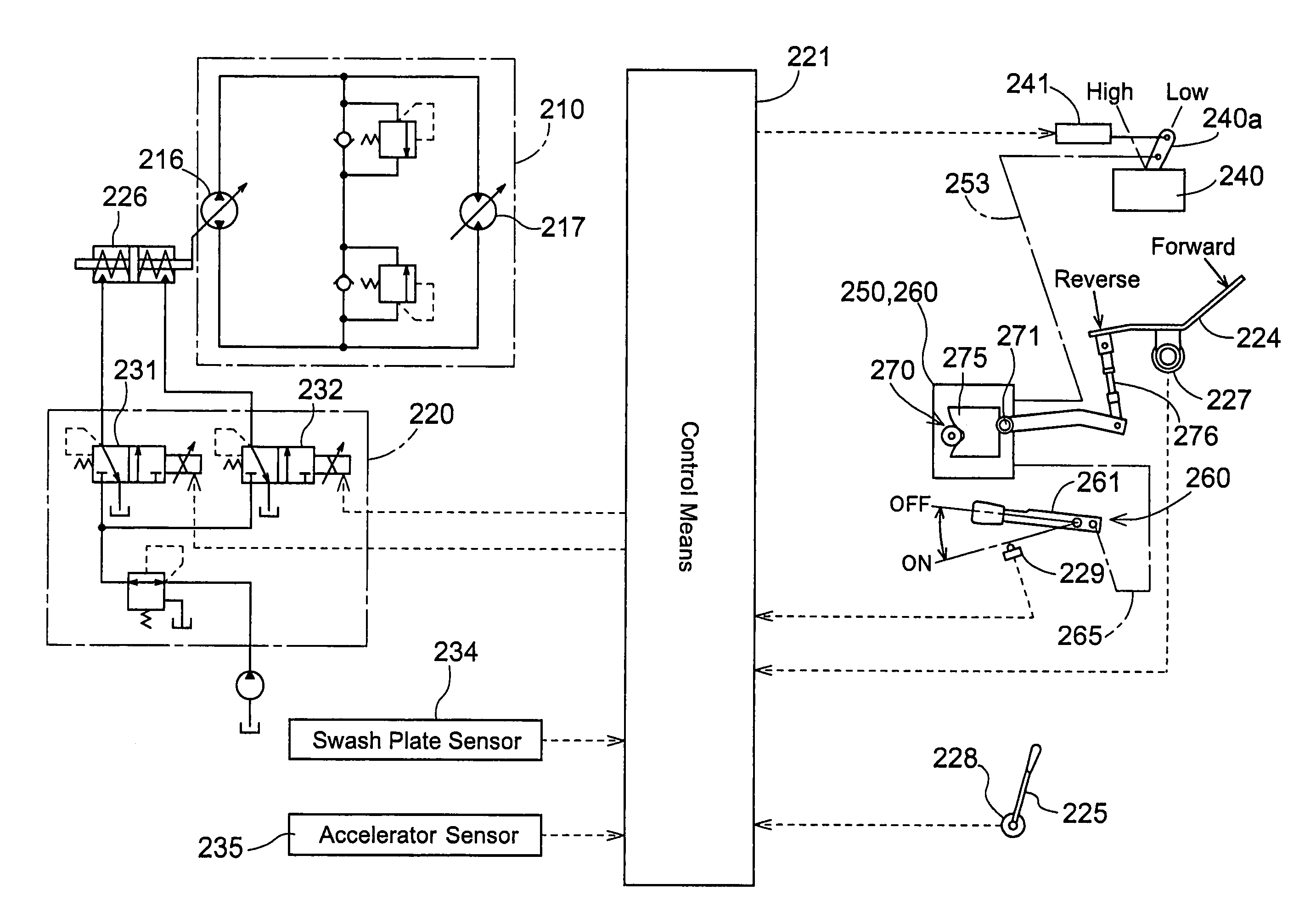
[0039]As shown in FIGS. 2-5, hydrostatic type continuously variable speed change device 10 has a axial plunger type variable displacement pump 16, axial plunger type variable displacement motor 17, etc. which are housed in the second casing part 4B, where the power from variable displacement pump 16, which is not speed-changed, is outputted as power for an operation and the speed-changed power from variable displacement motor 17 is outputted as power for traveling. The charge oil from charge pump 21 driven by the engine power is supplied to closed circuit 20 via charge oil path 22, check valve 23, etc. which...
PUM
 Abstract
Description
Claims
Application Information
 - R&D
- Intellectual Property
- Life Sciences
- Materials
- Tech Scout
- Unparalleled Data Quality
- Higher Quality Content
- 60% Fewer Hallucinations
Browse by: Latest US Patents, China's latest patents, Technical Efficacy Thesaurus, Application Domain, Technology Topic, Popular Technical Reports.
© 2025 PatSnap. All rights reserved.Legal|Privacy policy|Modern Slavery Act Transparency Statement|Sitemap|About US| Contact US: help@patsnap.com


