Front fold planter lift and fold hydraulic control system

a hydraulic control system and planter technology, applied in the field of work vehicles, can solve the problems of limiting the maximum raised height of the planter tool bar from the ground, limiting the maximum height of the road transport position, and the hydraulic control system of the invention has drawbacks, and achieves the effect of simple design and simple hydraulic control system

Active Publication Date: 2008-12-30
BLUE LEAF I P INC
View PDF11 Cites 45 Cited by
  • Summary
  • Abstract
  • Description
  • Claims
  • Application Information

AI Technical Summary

Benefits of technology

[0010]The present invention provides a hydraulic control system, an agricultural frame and a method of lifting and folding a front fold planter that addresses the drawbacks described above. The hydraulic control system of the invention allows for a master and slave cylinder arrangement wherein the master and slave can be operated independently of one another to effect distinct field transport and road transport heights. The hydraulic control system of the invention is also simple in design and parts for ready manufacturability.

Problems solved by technology

However, known hydraulic systems have drawbacks.
This is due to the fact that when an operator strokes a master cylinder controlling the height of the central wheels to the exclusion of the slave cylinder controlling the wing wheels, both cylinders typically bottom out thereby limiting the maximum raised height of the planter tool bar from the ground.
The limited maximum height of the road transport position has proved problematic when the planter needs to be moved long distances over ditches and other uneven surfaces.
Portions of the planter may not have adequate clearance to cross these uneven surfaces.
Likewise, the height (clearance of the tool bar from the ground) of the field transport position in many of these systems is unnecessarily high.
This system, while somewhat satisfactory for its intended purpose, exhibits drawbacks as the routing system is overly complex and costly to manufacture.

Method used


Image

  • Front fold planter lift and fold hydraulic control system
  • Front fold planter lift and fold hydraulic control system
  • Front fold planter lift and fold hydraulic control system

Examples


Embodiment Construction

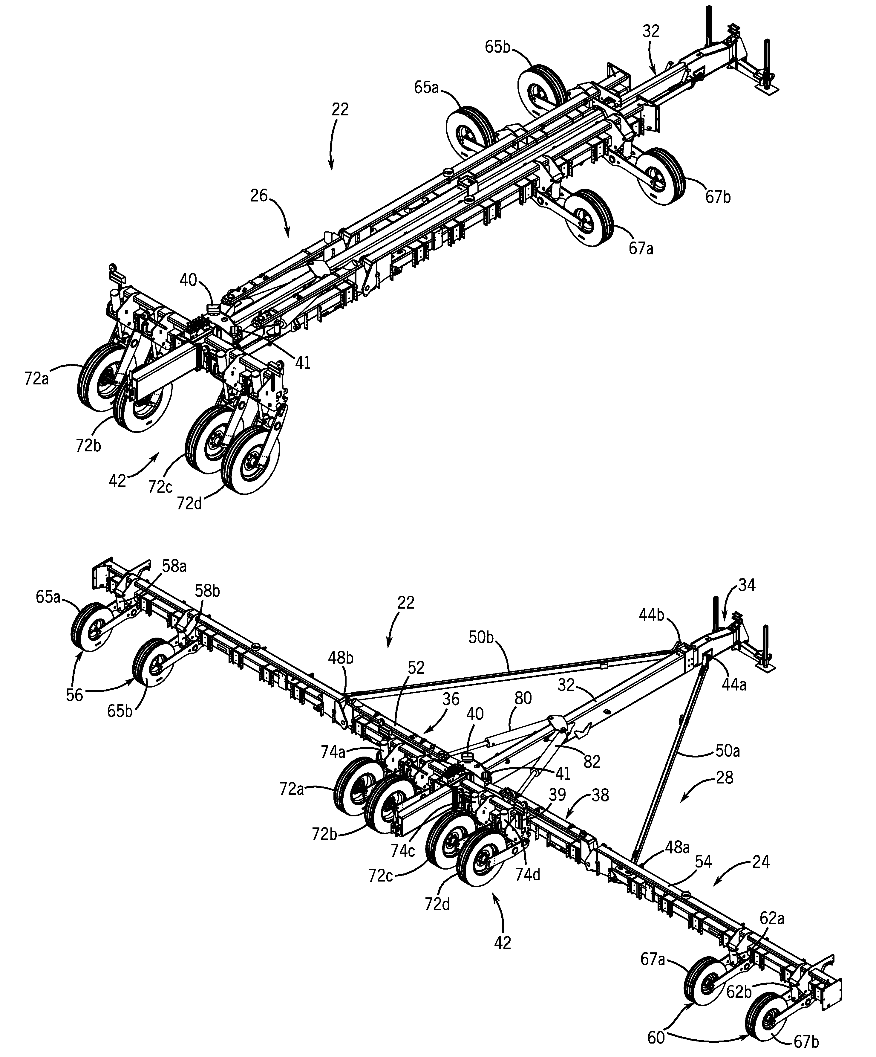
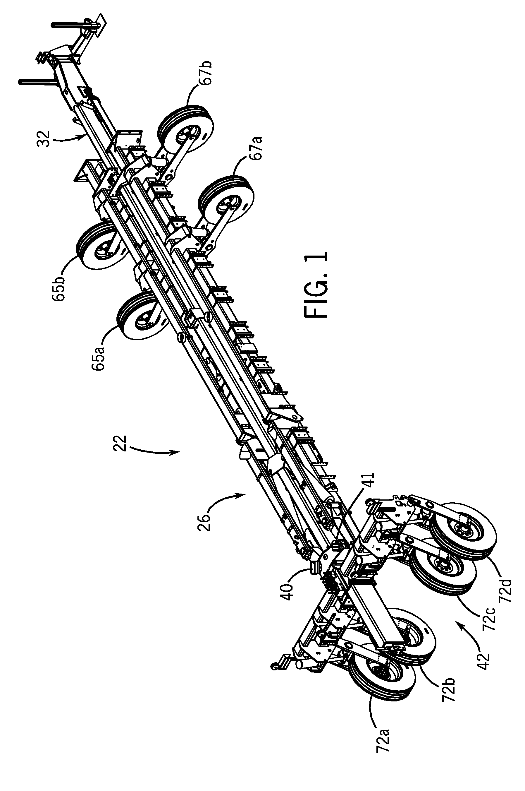
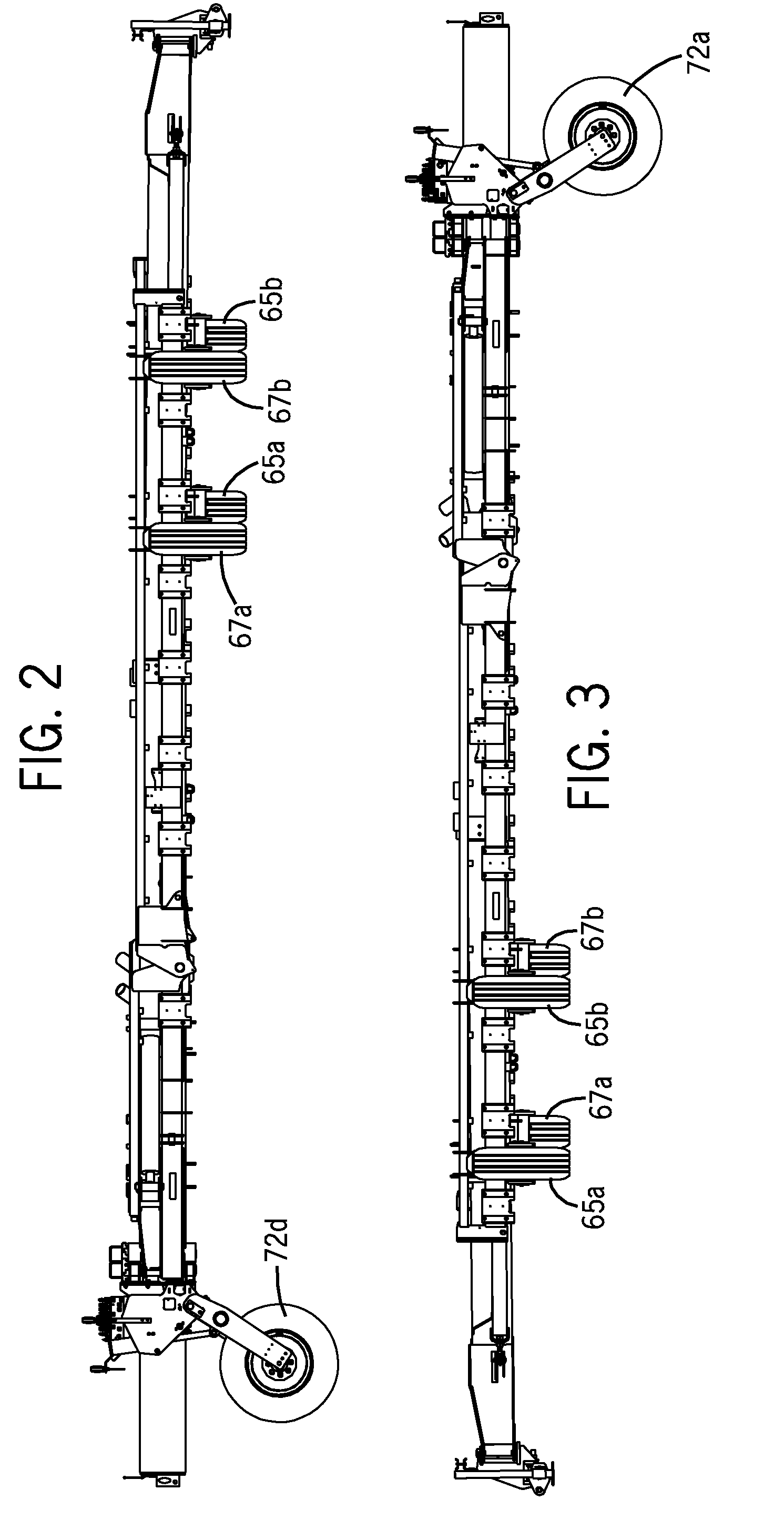
[0032]FIG. 10 illustrates a hydraulic control system 20 in accordance with the present invention in combination with a front fold planter 22, the system 20 generally configured to arrange an implement frame such as tool bar 24 of the front fold planter 22 (illustrated in FIGS. 1-9) in alternative road transport 26 (FIGS. 1-4), planting 28 (FIG. 5-8) and field transport 30 (FIG. 9) positions. The hydraulic control system 20 enables the tool bar 24 to achieve distinct field transport and road transport heights. The term “height” used herein refers to clearance of the tool bar 24 from the ground.

[0033]Referring to FIGS. 1-9, the exemplary front fold planter 22 is a conventional agricultural planter equipped to be drawn by a prime mover (not shown) across an agricultural field in a conventional manner. As best seen in the first position or planting position 28, illustrated in FIG. 5, the exemplary planter 22 planter includes a longitudinal central main frame 32. A support and connecting...


PUM


Abstract

A hydraulic control system for use with a front fold planter is configured to move the tool bar of the planter between a first height corresponding to a planting position, a second height corresponding to a field transport position and a third height corresponding to a road transport position. A first set of hydraulic cylinders is mounted to the tool bar for moving the frame between the first height, the second and the third height. A second set of hydraulic cylinders is mounted to the tool bar for moving the frame between the first height and the second height. The first and second set of cylinders are arranged in a master / slave relationship relative to each other and operable independent of each other.

Description

RELATED APPLICATIONS[0001]Not applicable.BACKGROUND OF THE INVENTION[0002]1. Field of the Invention[0003]The invention relates generally to work vehicles such as agricultural planters. More particularly, it relates to a hydraulic control system for an agricultural planter that includes a series of master cylinders having slave cylinders operably connected therewith. Even more particularly, it relates to a hydraulic control system wherein the master and slave cylinders can be operated independently of one another such that the master cylinder can be operated to effect distinct field transport and road transport heights.[0004]2. Discussion of the Related Art[0005]Conventional planters typically include a series of evenly spaced row planter units connected to an implement frame or tool bar so as to be towed across a field. The row planter units are generally configured to plant particulate product (i.e., seed, herbicide, pesticide, fertilizer, etc.) in evenly spaced individual rows. Th...

Claims


Application Information

Patent Timeline
Patent Type & Authority Patents(United States)
IPC IPC(8): A01B49/00A01B79/00A01C15/00A01C5/00A01C7/18
CPCA01B73/065A01C7/208Y10S111/90
Inventor BETTIN, LEONARD A.
Owner BLUE LEAF I P INC
Why Eureka
Try Eureka