
Anechoic visco-thermal liner

a visco-thermal liner and anechoic technology, applied in the field of acoustic liner, can solve the problems of limiting the range of frequencies that can be effectively attenuated, the number and size of openings that can be provided within the face sheet, and the practicability of limiting the range of openings, etc., to achieve a large opening area, large surface area, and thin overall thickness of the liner

Active Publication Date: 2008-12-30
RTX CORP
View PDF38 Cites 0 Cited by
  • Summary
  • Abstract
  • Description
  • Claims
  • Application Information

AI Technical Summary

Benefits of technology

"The patent describes a new type of liner that is used in aircraft to reduce noise. The liner has many small passages that help to dissipate the sound energy, converting it into heat energy. The passages are arranged in a way that allows for efficient noise reduction across a wide range of frequencies. The liner is also very thin, which makes it lighter and more compact than traditional liners. Overall, this new liner design can provide better noise reduction for aircraft interiors."

Problems solved by technology

Disadvantageously, there is a practical limit to the number and size of the openings that can be provided within a face sheet.
Further, although possible to tune the liner to attenuate noise of certain frequencies, such tailoring results in a limit to the range of frequencies that can be effectively attenuated.

Method used


Image

  • Anechoic visco-thermal liner
  • Anechoic visco-thermal liner
  • Anechoic visco-thermal liner

Examples


Embodiment Construction

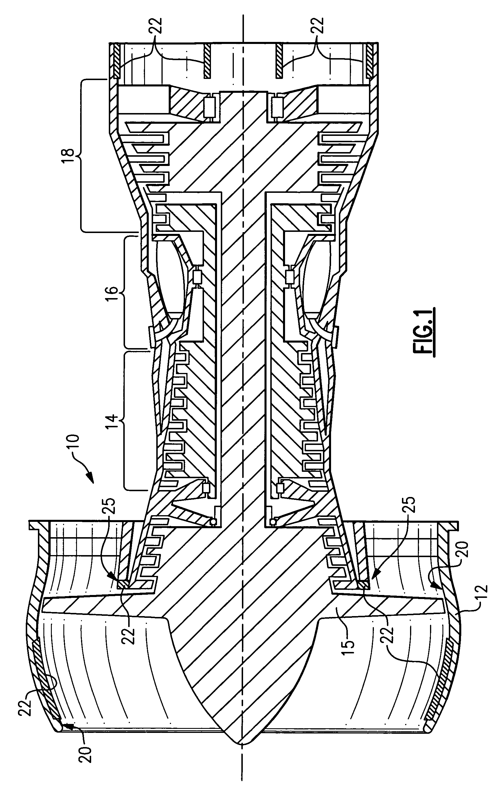
[0022]Referring to FIG. 1 an aircraft engine assembly 10 is schematically shown and includes a compressor fan 14 that compresses incoming air that is fed to a combustor 16. In the combustor 16, fuel is mixed with the compressed air and ignited. The resulting high speed exhaust gases drive a turbine 18 that in turn drives the compressor 14. The engine assembly 10 includes a housing 12 that protects the engine assembly from the environment and channels air to the compressor fan 15. The engine assembly 10 generates sound energy that propagates from the housing 12.

[0023]The housing 12 includes an inner surface 20 and acoustic liners 22. The acoustic liners 22 are disposed forward of compressor fan 14 and aft of the turbine 18. Although acoustic liners 22 are shown forward and aft in the housing 12, other locations within the housing 12 requiring sound attenuation may also include the acoustic liner 22 such as flow splitters 25. The acoustic liner 22 absorbs sound energy to reduce the ma...


PUM


Abstract

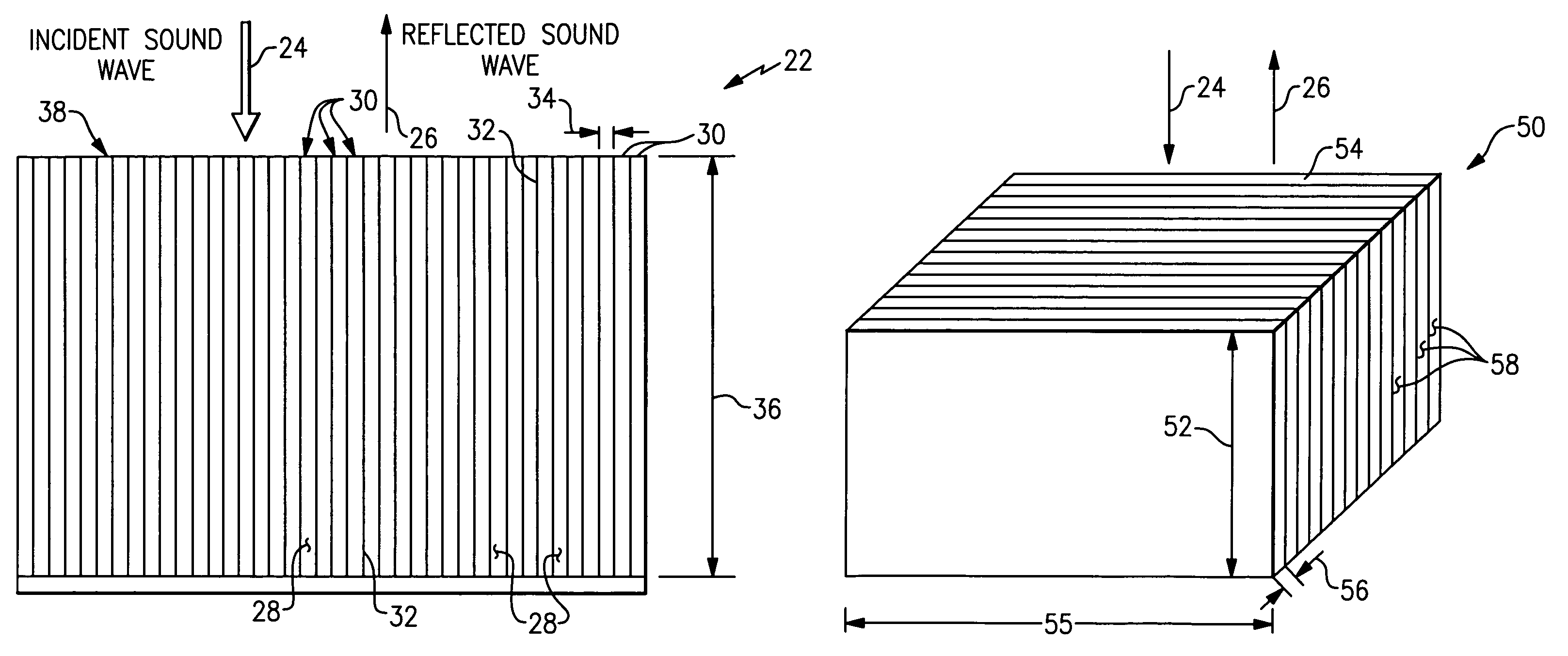
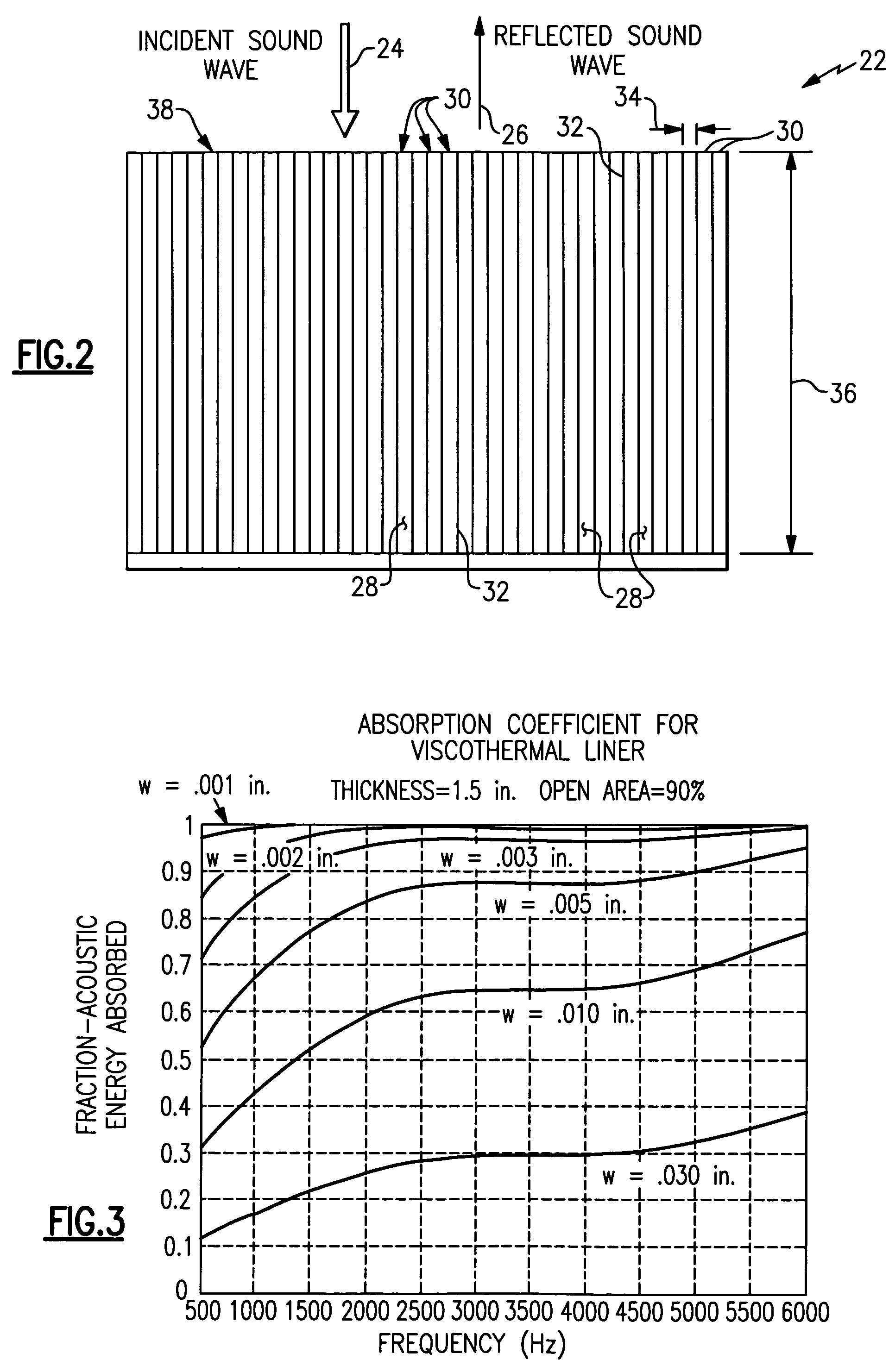
A liner assembly includes a plurality of aligned passages providing a large open area combined with openings much smaller than a length of the passages. The plurality of passages are disposed parallel with each other and include an opening transverse to incident sound waves. The passages are separated by walls and are blocked at an end distal from the openings. Sound waves incident on a face of the liner enter the passages and are dissipated by viscous losses. Sound energy is further dissipated as thermal energy to the walls of the passages. The long narrow passages provide the desired visco-thermal losses for sound energy in a broad frequency range.

Description

BACKGROUND OF THE INVENTION[0001]This invention generally relates to an acoustic liner. More particularly, this invention relates to an acoustic liner for minimizing reflection of sound from the acoustic liner face.[0002]Conventional nacelle liners include a noise attenuating structure covered by a face sheet including a plurality of openings. The openings communicate noise and acoustic energy through to the noise attenuating structure where the acoustic energy is dissipated. The face sheet includes an open area provided by the plurality of openings that is generally less than 20% of the total area of the face sheet. The open area provided by openings within the face sheet is configured to attenuate the most undesirable noise frequencies. The limited and tailored open area prevents sound energy of some frequencies from being dissipated and instead reflects that sound energy back into the nacelle. Greater open area can provide improvements to the range of noise frequencies that can b...

Claims


Application Information

Patent Timeline
Patent Type & Authority Patents(United States)
IPC IPC(8): G10K11/16E04B1/84E04B1/82G10K11/04
CPCB64D33/02B64D2033/0206Y02T50/60
Inventor PATRICK, WILLIAM P.
Owner RTX CORP
Learn More