Electric driving machine

a driving machine and electric technology, applied in the direction of manufacturing tools, stapling tools, nailing tools, etc., can solve the problems of unfavorable driving operation, unfavorable pneumatic driving machine operation, and the like, and achieve the effect of preventing unfavorable driving operation

Inactive Publication Date: 2008-12-30
KOKI HLDG CO LTD
View PDF10 Cites 38 Cited by
  • Summary
  • Abstract
  • Description
  • Claims
  • Application Information

AI Technical Summary

Benefits of technology

[0006]Accordingly, an object of the present invention is to provide an electric driving machine having a controller capable of preventing erroneous operation, which may otherwise arise because of a failure in the semiconductor switching element or the semiconductor integrated circuit device.
[0027]According to the present invention, the second switching element is connected in series with the solenoid acting as engagement / disengagement means, and the third switching element is connected in shunt with the solenoid. As a result, the third switching element is held in an ON state and the second switching element is held in an OFF state during a period in which driving of a fastener is not initiated. There is provided the controller for controlling the third switching element to the OFF state and the second switching element to the ON state at the time of fastener driving operation. Hence, the third switching element can prevent undesired initiation of driving of a fastener, which would otherwise be caused by a failure or other faulty operations of the second switching element.

Problems solved by technology

However, the pneumatic driving machine suffers a problem of workability being impaired by the hose which supplies compressed air to the driving machine from the air compressor and which always accompanying the driving machine.
Further, a heavy air compressor must be carried in conjunction with the pneumatic driving machine, and hence great inconvenience is encountered in moving and installing the air compressor.
In particular, when a failure, such as a thermal breakdown, has arisen in a semiconductor switching element or a microcomputer during the course of the flywheel being rotated by the electric motor, erroneous operation of the electric driving machine, such as commencement of unintended fastener driving operation, a failure in predetermined driving operation, or the like, is expected to arise.
This sometimes leads to a decrease in the precision of machining and working efficiency.

Method used


Image

  • Electric driving machine
  • Electric driving machine
  • Electric driving machine

Examples


Embodiment Construction

[0056]An embodiment in which the present invention is applied to an electric driving machine will be described hereunder by reference to the drawings. In addition to including descriptions of characteristics of the present invention, the following descriptions of an embodiment encompass descriptions of characteristics of other inventions in order to facilitate comprehension of the configuration and advantages of an overall electric driving machine of the present embodiment. Throughout the drawings for explanation of the embodiment, members having the same functions are assigned the same reference numerals, and their repeated explanations are omitted.

[0057][Built-up Structure of an Electric Driving Machine]

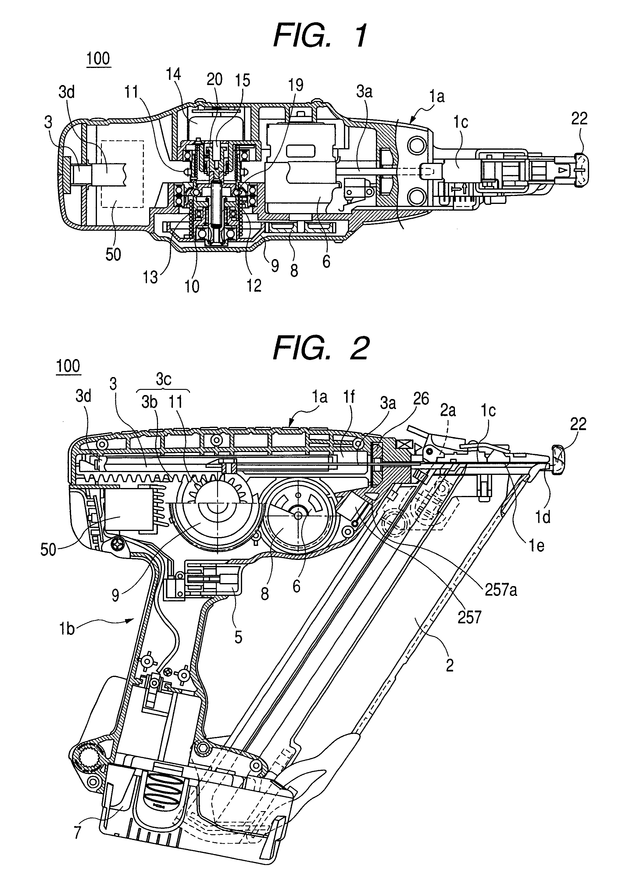
[0058]A built-up structure of an electric driving machine of the embodiment of the present invention will first be described by reference to FIGS. 1 through 5.

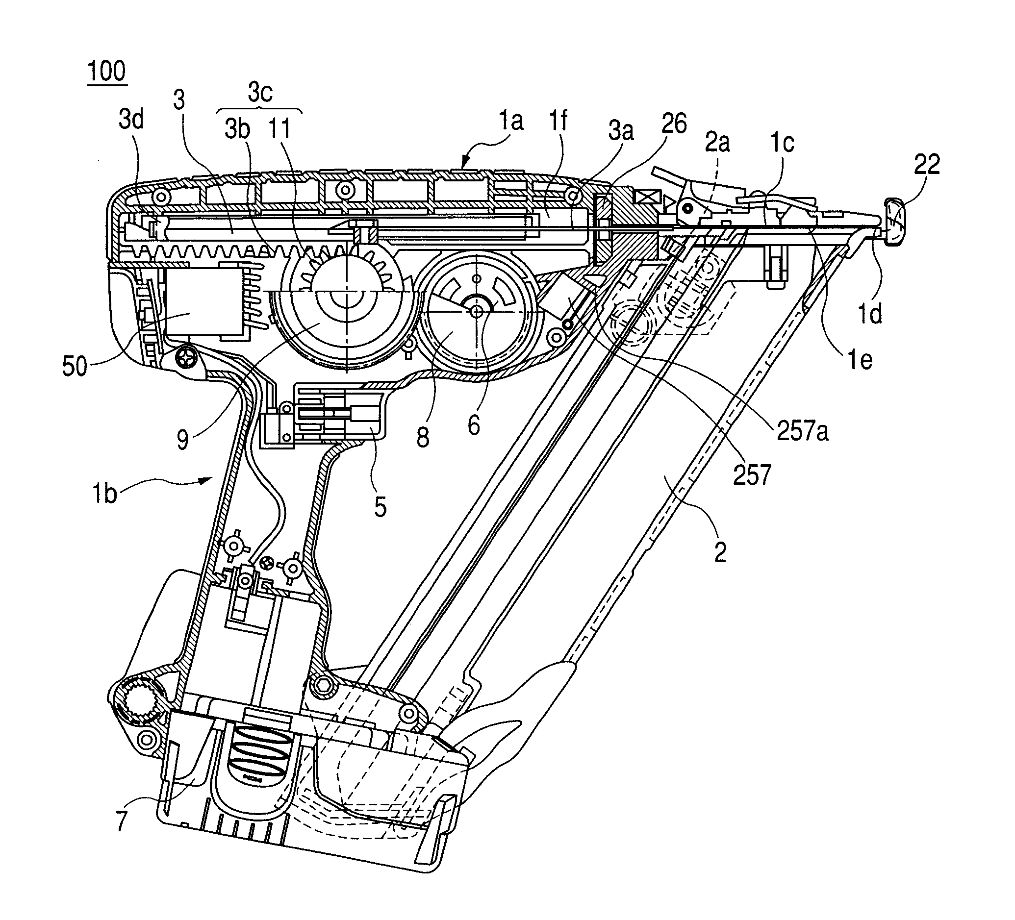
[0059]As shown in a top view of FIG. 1 and a side view of FIG. 2, an electric driving machine 100 comprises a main body hou...


PUM

PropertyMeasurementUnit
source voltageaaaaaaaaaa
battery voltage VBATaaaaaaaaaa
voltageaaaaaaaaaa

Abstract

An electric driving machine has a motor for rotating a flywheel, power transmission for converting rotational drive force of the flywheel into rectilinear drive force and transmitting the rectilinear drive force to an actuator which fires a fastener, and engagement / disengagement arrangement which transmits the rotational drive force of the flywheel to a driver blade of interrupts transmission of the rotational drive force. The electric driving machine is provided with a second switching element connected in series with the engagement / disengagement arrangement and a third switching element connected in shunt with the engagement / disengagement arrangement. When a push lever switch is in an OFF position where driving of a fastener is not ready, the third switching element is held in an ON state.

Description

CROSS-REFERENCE TO RELATED APPLICATIONS[0001]This application is based on and claims the benefit of priority from the prior Japanese patent application No. 2006-248817, filed on Sep. 14, 2007; the entire contents of which are incorporated herein by reference.TECHNICAL FIELD[0002]The present invention relates to an electric driving machine which uses a motor as a firing drive source for driving a fastener, such as nails, staples, and the like. The present invention relates particularly to an electric driving machine including a power transmission mechanism—which has a clutch mechanism for transmitting rotational drive force of a motor in the electric driving machine, as rectilinear drive force, to an actuator having a drive blade for driving the fastener—and a controller for controlling operation timing of the motor.BACKGROUNDDescription of the Related Art[0003]A pneumatic driving machine—which guides air compressed by an air compressor through use of an air hose and uses the thus-gu...

Claims


Application Information

Patent Timeline
Patent Type & Authority Patents(United States)
IPC IPC(8): B25C1/06
CPCB25C1/06
Inventor SHIMA, YUKIHIROINANIWA, MASAHIROODA, HIROYUKIUEDA, TAKASHINAKANO, YOSHIHIRO
Owner KOKI HLDG CO LTD
Why Eureka
Try Eureka