Data processing apparatus, printing apparatus and method of creating mask

a data processing apparatus and printing apparatus technology, applied in the field of creating masks, can solve problems such as granularity so far, and the problem of printing image beading, and achieve the effect of reducing beading

Active Publication Date: 2008-12-30
CANON KK
View PDF6 Cites 15 Cited by
  • Summary
  • Abstract
  • Description
  • Claims
  • Application Information

AI Technical Summary

Benefits of technology

[0023]An object of the present invention is to provide a data processing apparatus, a printing apparatus, and a method of creating a mask that are capable of reducing the beading caused by the interference between a block pattern, which is a driving pattern for each nozzle array at the time of printing with the use of a plurality of nozzle arrays for the same color, and a mask.
[0032]The above configuration allows mask processing to be performed on dot data with the use of a mask having an arrangement of print permitting areas in which low-frequency components are fewer than high-frequency components in a pattern obtained by the logical product of the arrangement of print permitting areas in the mask and an arrangement of driving permitting areas in a driving pattern for each nozzle group. This improves the dispersiveness of the print permitting area arrangement in the mask itself to be created. Also, respective arrangements of dots obtained by allocating the dot data processed with the use of the mask to a plurality of nozzle arrays to print based on the allocated data become improved in dispersibility. Further, an uneven distribution of a dot arrangement to one of the nozzle arrays is reduced. That is, the interference between the print permitting areas in the mask and a plurality of driving patterns is appropriately reduced, whereby an image printed with the use of the plurality of nozzle arrays becomes improved in dispersibility without any uneven distribution of dots. As a result, beading occurring during printing can be reduced among others, and thereby image quality can be improved.

Problems solved by technology

In ink jet printing apparatuses, granularity has so far been seen as a problem when compared to silver salt photographs.
Meanwhile, if a printing speed is increased in general, for example, if a printing configuration in which a plurality of nozzle arrays such as the above 2 nozzle arrays are provided and a printing speed is increased by several times without the change in driving frequency is employed, a problem of beading in a printed image may arise.
In such a case, although the printing medium may eventually absorb a total amount of the ink applied depending on a type of the printing medium, the absorption may not be able to follow the applying speed, and therefore ink droplets, which have not been absorbed at the surface of the printing medium, may come into contact with each other during printing.
Then, a relatively increased size of ink droplet caused by combination due to the contact may become highly visible on a resulting image to thereby reduce image quality.
As a result, such a grain itself or the presence of such grains that are irregularly distributed causes an adverse effect on an image, which is called “beading”.
For example, if inter-reactive printing liquids are applied in the same scanning, the contacted liquids are combined by a strong chemical reaction, which may cause the formation of a grain nucleus.
For this reason, dispersibility in relation to, for example, dots in another color plane printed in the same scanning or dots in a plane printed in another scanning, is poor, which may cause grains.
Such uneven use of the nozzles is likely to result in poor dispersibility of printed dots to thereby cause beading due to the above-described grains.
Thus, if the interferences in dot positions between the mask and a plurality of planes with a plurality of block patterns are present, the dispersibility in a dot arrangement of an image to be eventually printed may become poor, causing the problem of beading.

Method used


Image

  • Data processing apparatus, printing apparatus and method of creating mask
  • Data processing apparatus, printing apparatus and method of creating mask
  • Data processing apparatus, printing apparatus and method of creating mask

Examples


embodiment 1

sk for Two Pass Printing

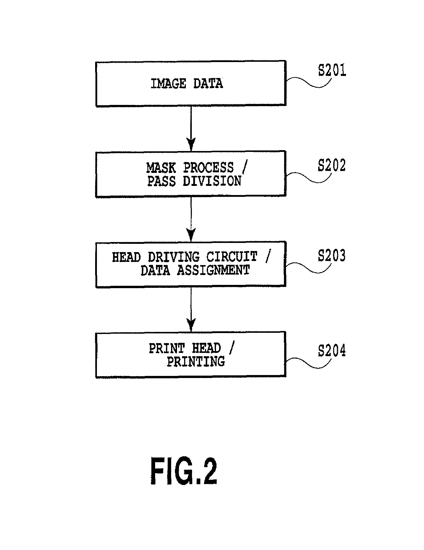
(Summary of the Embodiment)

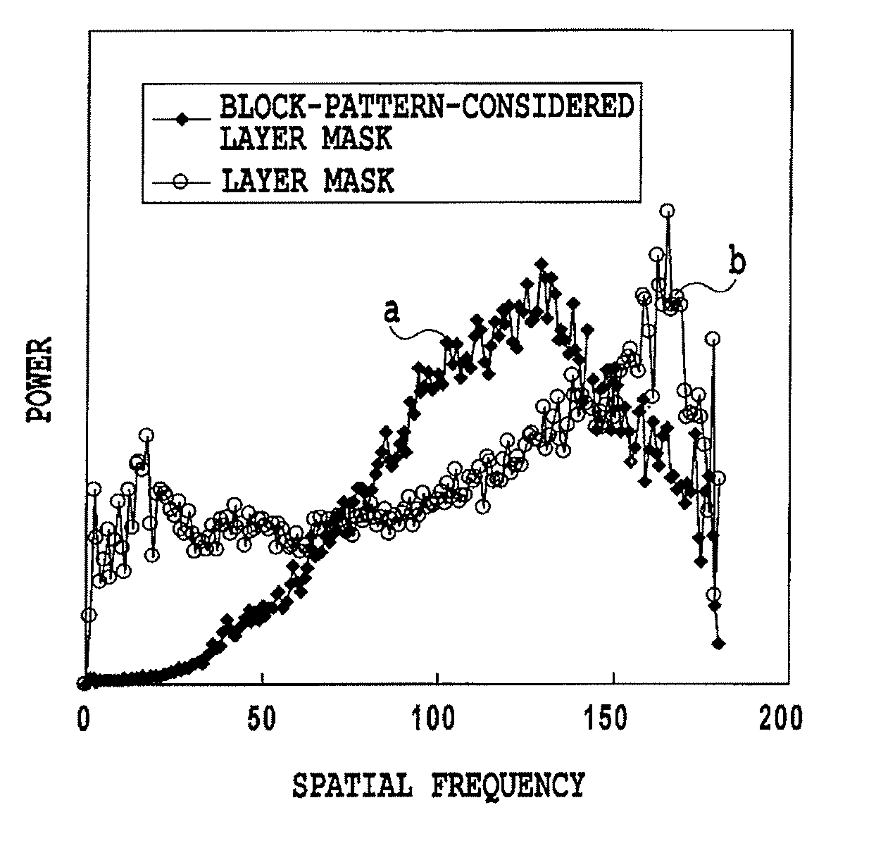
[0122]This embodiment relates to multi-pass printing of two-pass in which an image is completed by twice of scanning by using one print head equipped with a nozzle array ejecting cyan (C) ink as a printing element. Masks used for the two-pass printing have respective patterns whose interference with the block pattern for driving the print head are reduced and which are well dispersed. This prevents dots formed by each scanning from being unevenly distributed in number. Furthermore, since dots are dispersedly formed in each scanning, even if there is a deviation of printing position for example, texture that may be caused by the deviation is visually unobtrusive, thus suppressing adverse effects on image quality.

[0123]FIG. 10 is a diagram schematically showing mainly the positional relationship of a print head, a mask pattern and a print medium in order to illustrate two-pass printing. A print head is equipped with two nozzle arrays ...

embodiment 2

sk for Four-pass Printing

(Outline of this Embodiment)

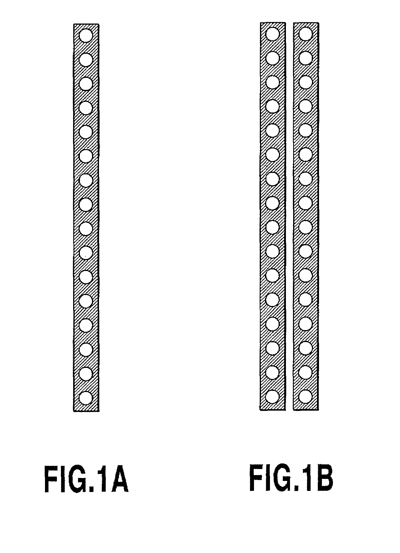
[0165]A second embodiment of the present invention relates to the multi-pass printing of four-pass in which an image is completed in four times of scanning (twice of reciprocal scanning) by the use of the two nozzle arrays A and B shown in FIG. 13A for ink of each of cyan (C), magenta (M), and yellow (Y). Also, masks to be used for the four-pass printing are those in which block patterns are considered. Regarding each of the masks in this embodiment, the interferences with the block patterns are reduced as in the first embodiment, and also those with the other masks are reduced. This enables the occurrence of beading caused by the aggregation of ink droplets ejected during a plurality of times of scanning to be reduced among others.

[0166]In this embodiment, the order of printing is: a first pass of the nozzle array A for cyan,→a first pass of the nozzle array B for cyan,→a first pass of the nozzle array A for magenta,→a first pass...

embodiment 3

on Mask for Two-pass Printing

[0181]A third embodiment of the present invention relates to reducing the interference or increasing dispersibility between a gradation mask and a block pattern in the case of using the gradation mask. Specifically, likewise as above-mentioned embodiments, repulsive potential between the gradation mask of this embodiment and the block pattern is calculated to determine the arrangement of print permitting areas.

[0182]A gradation mask has a print ratio (ratio of print permitting areas arranged in a predetermined region) corresponding to nozzle positions. In this embodiment, the number of print permitting areas that meet the print ratio corresponding to each nozzle number is arranged. The planes of block patterns to be considered for calculating repulsive potential are two planes B1 and B2 shown in FIG. 12, likewise as in the first embodiment.

[0183]A method for creating masks is basically same as that of the first embodiment, except that in placing the prin...


PUM


Abstract

Beading caused by interferences between block patterns, which are driving patterns of two nozzle arrays at the time of printing with the use of the two nozzle arrays for the same color, and a mask is reduced. Specifically, when the mask is created, repulsive potentials are calculated between the mask and planes with the block patterns. That is, when a placement of a print permitting area in the mask is determined, the repulsive potentials are calculated between the mask and dots in the planes with the block patterns, and then the print permitting area is placed on the most dispersive position with the lowest energy. This allows the print permitting areas to be well dispersed in terms of the overlaps between the block patterns and the mask.

Description

BACKGROUND OF THE INVENTION[0001]1. Field of the Invention[0002]The present invention relates to a data processing apparatus, a printing apparatus, and a method of creating a mask. More particularly, the present invention relates to a dot data generation processing for dividing dot data with the use of a mask into respective dot data to be used for a plurality of times of scanning of a print head, and based on the divided dot data, performing printing with the use of a plurality of arrays of printing elements or a plurality of heads, in regard to printing elements for the same color.[0003]2. Description of the Related Art[0004]With the diffusion of information processing equipment such as personal computers in recent years, printing apparatuses as image forming terminals have also been rapidly developing and diffusing. Of those various printing apparatuses, an ink jet printing apparatus that executes ink ejection to perform printing on a print medium such as paper, cloth, plastic sh...

Claims


Application Information

Patent Timeline
Patent Type & Authority Patents(United States)
IPC IPC(8): B41J2/205
CPCG06K15/107
Inventor NOGUCHI, ERIMARUMOTO, YOSHITOMO
Owner CANON KK
Why Eureka
Try Eureka