Wire surface spraying device

A technology of surface spraying and wire rod, which is applied in the direction of spraying device, electrostatic spraying device, liquid spraying device, etc. It can solve the problems of discounting the performance of the coating layer, affecting the integrity, uniformity and density of the wire rod surface, and falling off.

Active Publication Date: 2020-04-24
CHONGQING MATERIALS RES INST
View PDF12 Cites 0 Cited by
  • Summary
  • Abstract
  • Description
  • Claims
  • Application Information

AI Technical Summary

Problems solved by technology

Due to the special material on the surface of some special wires, when traditional dipping and brushing processes are used, the surface materials of the wires are prone to softening, damage, shedding, and structural damage during the process of water absorption, friction, or stress. The integrity, uniformity and density of the wire surface are compromised, resulting in greatly reduced performance of the coating layer, and the quality of the wire cannot be guaranteed
Therefore, it is necessary to design a wire surface spraying device to minimize the contact with the wire surface material during the coating process, so as to prevent the wire surface material from softening, breaking, falling off, and structural damage, which will affect the performance of the coating layer.

Method used


Image

  • Wire surface spraying device

Examples


Embodiment Construction

[0020] An embodiment of the present invention:

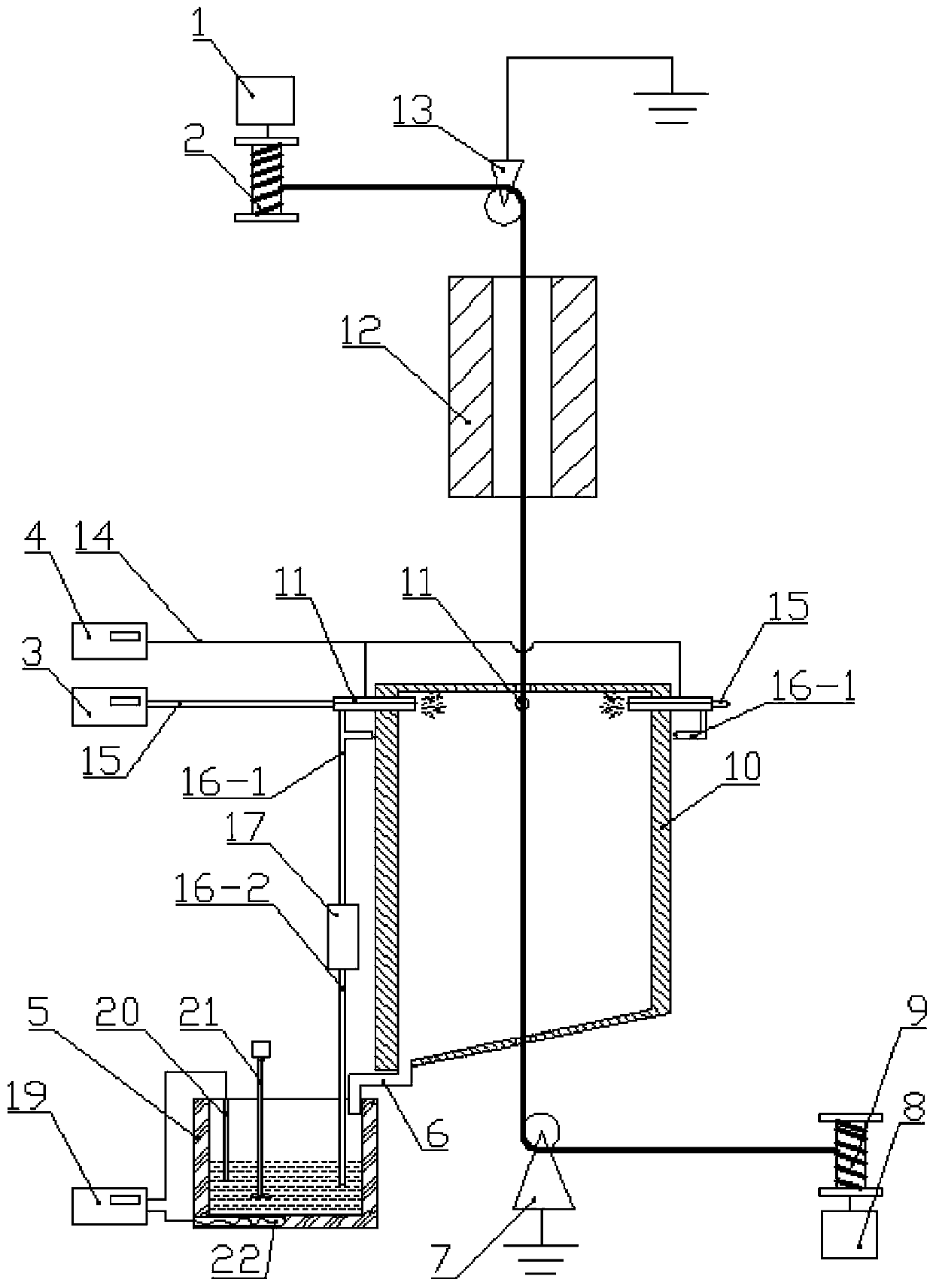
[0021] see figure 1 , a wire surface spraying device, comprising a pay-off mechanism 8, a take-up mechanism 1, a slurry box 5, a spray tank 10 and a drying furnace 12 are arranged between the pay-off mechanism 8 and the take-up mechanism 1, and the The pay-off mechanism 8 is located below the spray tank 10, the first guide wheel 7 is arranged between the pay-off mechanism 8 and the spray tank 10, the drying furnace 12 is located above the spray tank 10, and the take-up mechanism 1 is located in the drying furnace Above 12, a second guide wheel 13 is arranged between the wire take-up mechanism 1 and the drying furnace 12, and the first guide wheel 7 and the second guide wheel 13 are grounded, so that the wire rod passing through the guide wheels forms a positive pole, and the first guide wheel 7. The second guide wheel 13 can also control the wire on a vertical line, and avoid the situation that the slurry on the surface of the ...


PUM


Abstract

The invention discloses a wire surface spraying device. The device comprises an unwinding mechanism, a winding mechanism and a slurry box; a spraying tank and a drying furnace are arranged between theunwinding mechanism and the winding mechanism, the unwinding mechanism is located below the spraying tank, a first guiding wheel is arranged between the unwinding mechanism and the spraying tank, thedrying furnace is located above the spraying tank, the winding mechanism is located above the drying furnace, and a second guiding wheel is arranged between the winding mechanism and the drying furnace; wire passing holes allowing a wire to pass through are formed in the upper end wall and the lower end wall of an inner cavity of the spraying tank, a plurality of electrostatic spraying guns are distributed on the side wall of the inner cavity of the spraying tank, the electrostatic spraying guns are connected with an electrostatic generator through wires, and the electrostatic spraying guns are connected with an air compressor through vent pipes; and the spraying tank is connected with a slurry recycling pipe, the downstream end of the slurry recycling pipe is located in the slurry box, the electrostatic spraying guns are connected with a suction pump through slurry conveying pipes, the inlet of the suction pump is connected with a material suction pipe which is inserted into the slurry box, the slurry box is provided with an electric heater, and the electric heater is connected with a temperature controller through a wire.

Description

technical field [0001] The invention relates to the technical field of wire surface coating, in particular to a wire surface spraying device. Background technique [0002] Surface coating technology refers to the technology of coating a layer of new materials on the surface of materials to improve surface properties, such as electroplating, painting, thermal spraying and vapor deposition technology, etc. In the production process of wire used for electrical conduction, it is often necessary to coat the surface of the wire to improve the insulation, wear resistance, waterproof, and oxidation resistance of the wire surface, which is usually achieved by dipping, brushing, and sheathing. . Due to the special material on the surface of some special wires, when traditional dipping and brushing processes are used, the surface materials of the wires are prone to softening, damage, shedding, and structural damage during the process of water absorption, friction, or stress. The inte...

Claims


Application Information

Patent Timeline
Patent Type & Authority Applications(China)
IPC IPC(8): B05B16/20B05B9/04B05B5/025B05B13/02B05B15/25B05B14/40
CPCB05B16/20B05B9/0413B05B5/0255B05B13/0221B05B15/25B05B13/0278B05B14/40Y02P70/10
Inventor 王小宇刘奇韩校宇姚志远薄新维何浩然王焱辉刘成超
Owner CHONGQING MATERIALS RES INST
Why Eureka
Try Eureka