Liquid ejection head and liquid ejection device

a liquid ejection device and liquid ejection technology, which is applied in the direction of printing, inking apparatus, etc., can solve the problems of insufficient supply of liquid to the flow path, nozzles b>18/b> may be clogged with dust, and the liquid cannot be ejected from the nozzles

Inactive Publication Date: 2008-12-30
SONY CORP
View PDF18 Cites 16 Cited by
  • Summary
  • Abstract
  • Description
  • Claims
  • Application Information

AI Technical Summary

Benefits of technology

[0046]In the above invention, the liquid ejection head is provided with two individual flow paths connecting to the liquid chamber. Further, the width of the liquid chamber is formed larger than the flow path width of the individual flow paths. Accordingly, even if bubbles are generated in one of the individual flow paths and a liquid cannot be supplied to the liquid chamber therefrom, the liquid can be supplied thereto from the other individual flow path. Further, even if the two individual flow paths are provided, pressure necessary to eject the liquid can be maintained by making the flow path width of the individual flow paths narrower than the width of the liquid chamber.

Problems solved by technology

In the head 1 of the conventional technology described above, a problem arises in that, first, the liquid fails to be ejected from the nozzles 18 and is supplied to the flow paths in an insufficient amount because dusts and the like come into the flow paths and the nozzles 18.
In liquid ejection devices such as inkjet printers and the like, however, the nozzles 18 may be clogged with dusts and the like because the structure thereof is such that a liquid is ejected from nozzles 18 having a diameter of several microns.
In particular, since an increase in the number of nozzles as in a line head increases the probability of failed injection of a liquid from the nozzles 18, dusts and the like must be more strictly managed, from which a problem of an increase in cost arises.
Further, bubbles may be generated in the liquid as a result of an increase in the temperature of the head 1, from which a problem arises in that the liquid is ejected in an insufficient amount due to the bubbles.
Further, since the liquid is supplied into the liquid chambers 3a passing among the bubbles, insufficient ejection characteristics are often maintained fixedly.
In contrast, since a portion surrounded by a bubble is composed of a gas, it has a bad coefficient of thermal conductivity, thereby the heat of a heating portion is liable to be accumulated in the portion because it is not cooled by the liquid.
As a result, a problem arises in that the bubble is expanded.
Further, there is also a problem in that the liquid is ejected unevenly by the impact waves in ejection coupled particularly with the existence of bubbles.
In the case, however, since the size of dusts and the like passing through the filter is increased, large dusts and the like are liable to come into the individual flow paths 3d.
When bubbles are generated or remain, they are encountered with the impact waves, thereby the bubbles are liable to be drawn and the uneven liquid ejection is liable to be caused.
In contrast, in a line system, in which image formation is completed by ejecting droplets once and the overlapped writing cannot be executed in principle, the uneven liquid ejection cannot be recovered different from the serial system.

Method used


Image

  • Liquid ejection head and liquid ejection device
  • Liquid ejection head and liquid ejection device
  • Liquid ejection head and liquid ejection device

Examples


example 1

[0168]FIGS. 14A and 14B are views showing a result that a reduction in impact waves is confirmed (as a result of photographing) in the conventional structure and in the structure of the embodiment.

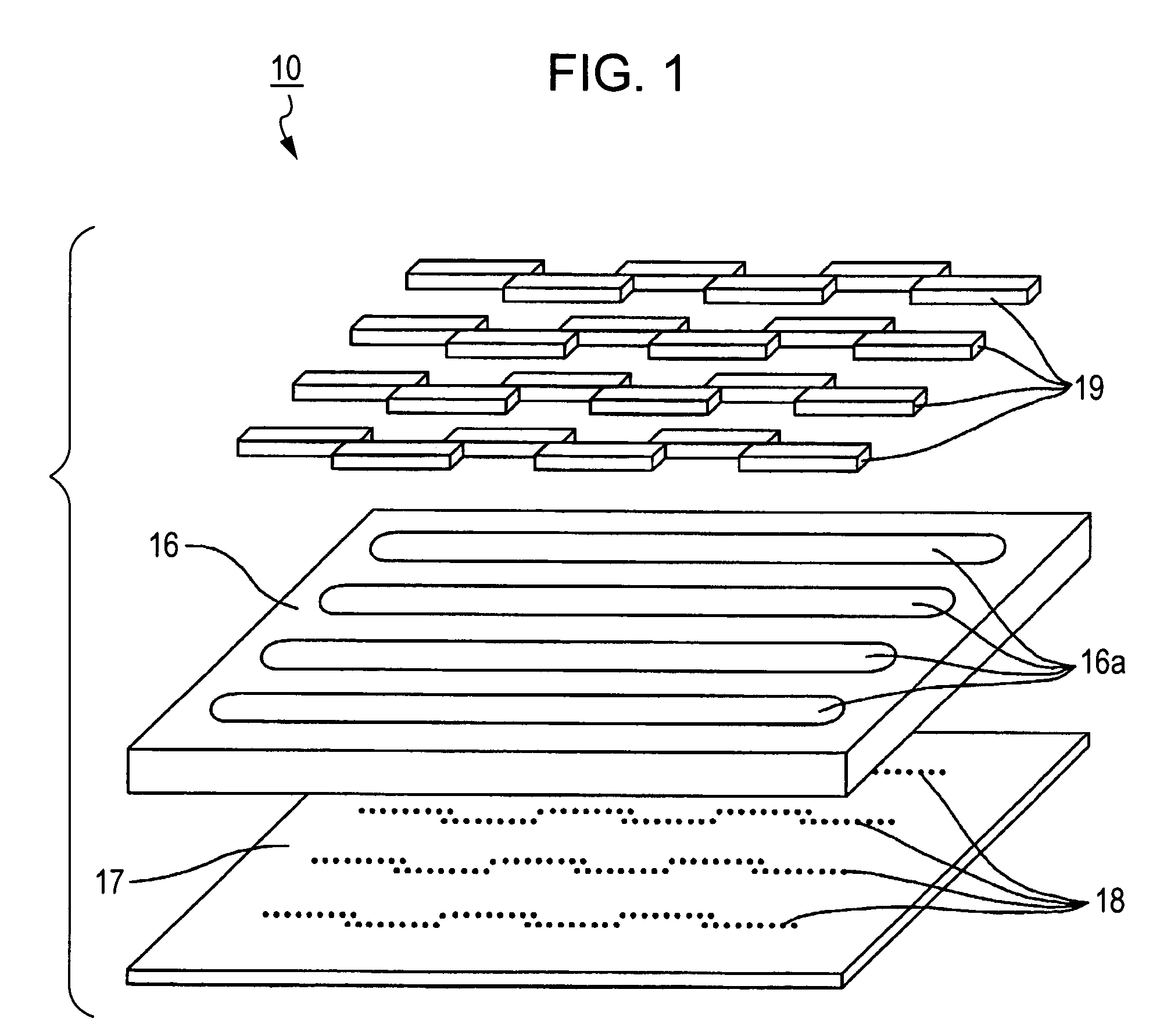
[0169]In an example 1, a semiconductor substrate 11, on which 320 heating elements 12 are disposed at 600 DPI (nozzle intervals are set to 4.2 μm), is used (size: about 16 mm×16 mm).

[0170]A nozzle sheet 17 composed of a transparent acrylic resin is used so that an internal behavior can be observed. The result of experiment shown in FIGS. 14A and 14B corresponds to the view shown in FIG. 12.

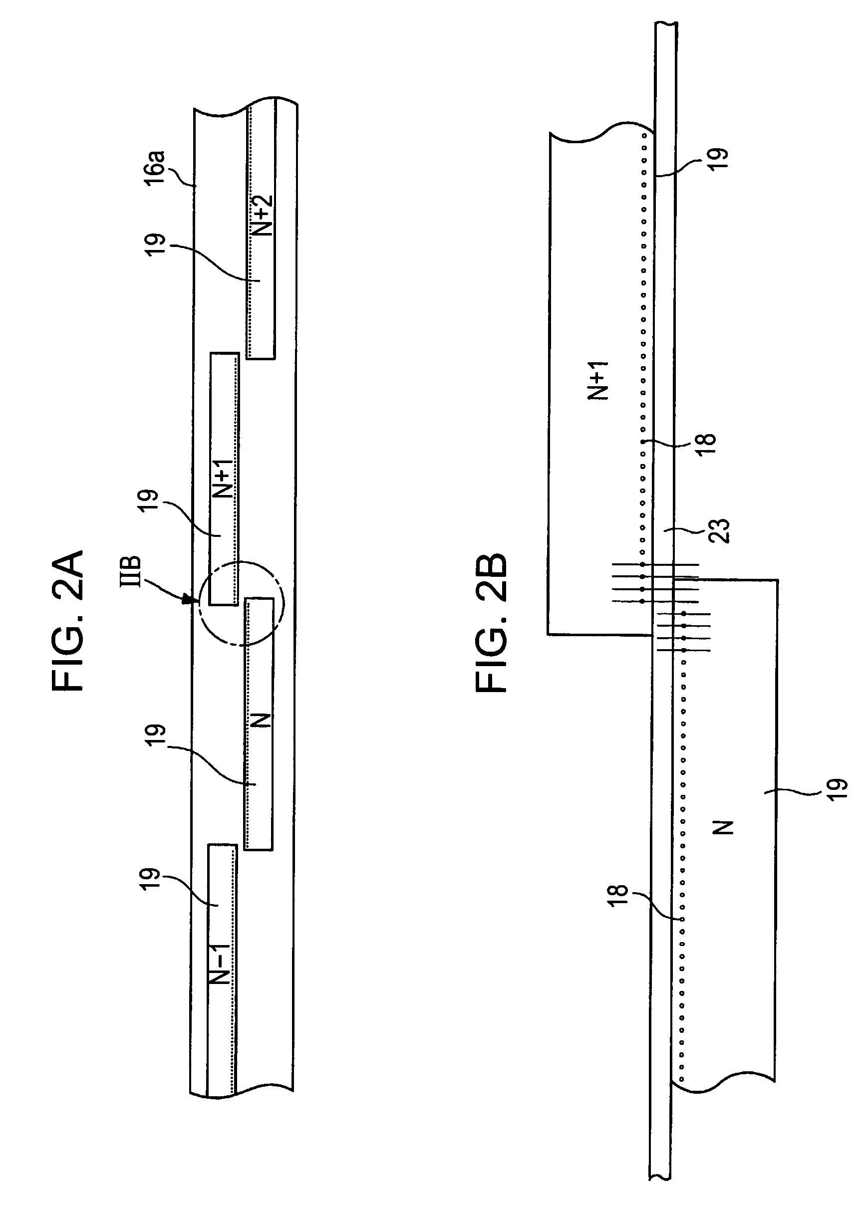
[0171]In the conventional structure of FIG. 14B, nozzles 18 arranged linearly. In contrast, in the example, nozzles 18 are arranged zigzag as described above.

[0172]In FIGS. 14A and 14B, the nozzles 18 seem black just after they eject the liquid because a liquid surface is intensely fluctuated by the influence of impact waves. Although the longitudinal lines of the heating elements 12 disposed below are n...

example 2

[0173]FIG. 15 is a plan view showing a specific structure of a head used in an example 2. As shown in FIG. 15, the head used in the example 2 is provided with a liquid storage region 28 having pillars 28a interposed between the outlets of the second individual flow paths 13e and the wall of the barrier layer 13. A filter 25 disposed in a common flow path 23 is the same as the filter 25 shown in FIG. 9.

[0174]FIG. 16 is a view showing how bubbles are discharged using a head having the structure shown in FIG. 15 as a result sequential photographing. FIG. 16 shows the behavior of bubbles discharged in the sequence of “1”, “2” . . . “9”.

[0175]In “1” of FIG. 16, bubbles were injected from the nozzles, and the space between the liquid storage region 28 and the second individual flow paths 13e was clogged with the bubbles. Then, when a liquid ejecting operation was repeated using a third nozzle 18 from the left side as shown in “1”, the bubbles were gradually discharged from the nozzle 18.

example 3

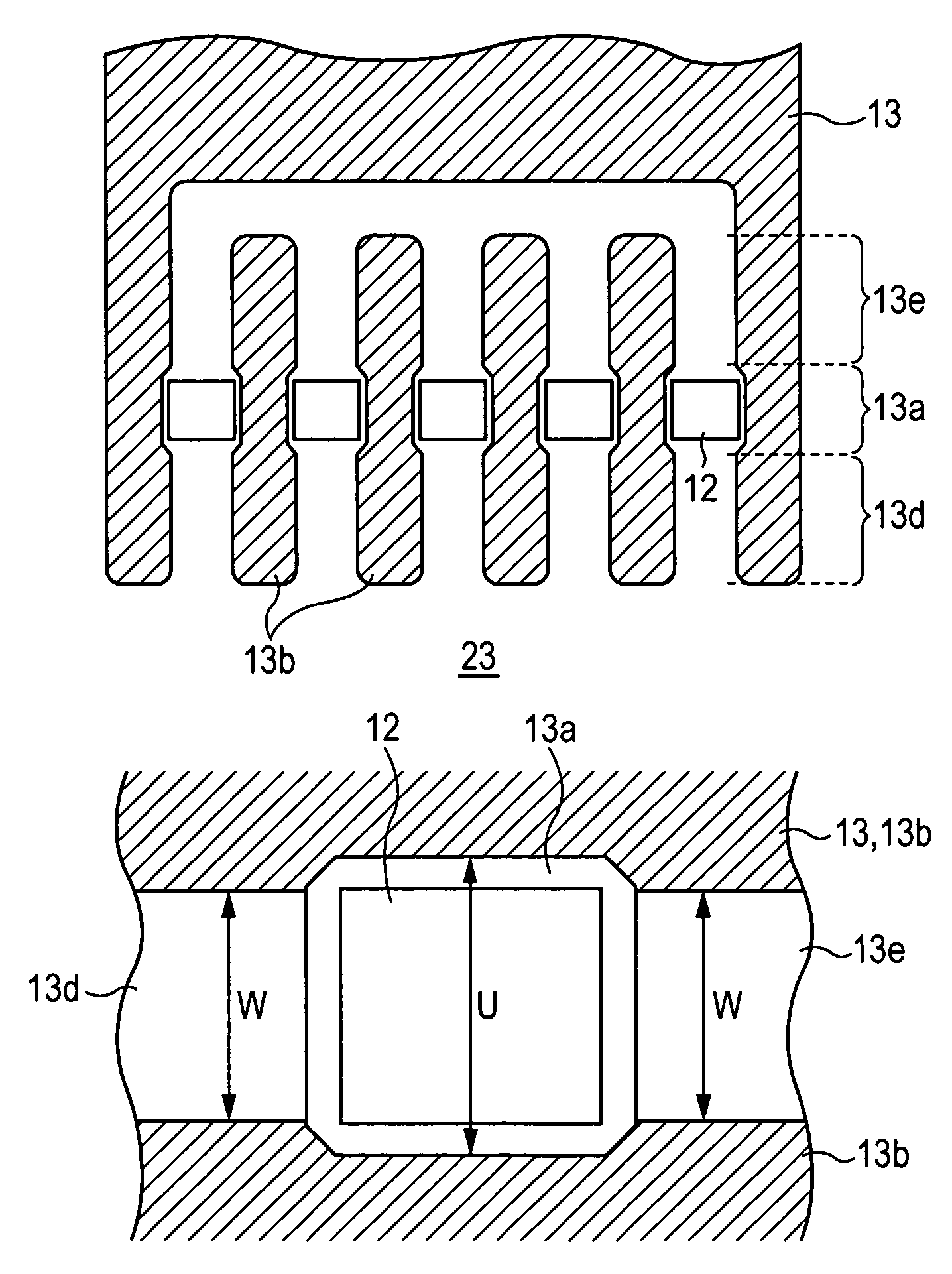
[0176]FIGS. 17A and 17B are views showing a part of a mask view of a prototype head (nozzle pitch: 42.3 μm, resolution: 600 DPI). In FIGS. 17A and 17B, an upper side is a common flow path 23 side.

[0177]FIG. 17A shows an example corresponding to the arrangement shown in FIG. 11 (the second embodiment described later in detail), FIG. 17B shows an example corresponding to the arrangement shown in FIG. 3.

[0178]That is, In FIG. 17A, adjacent second individual flow paths 13e communicate with each other. Further, FIG. 17B, all the second individual flow paths 13e communicate with each other.

[0179]Further, the filter 25 is composed of triangular-prism-shaped pillars. Further, the heating elements are arranged zigzag.

[0180]When images were actually printed with the heads, burst errors (wide portions with uneven color and voided portions in monochrome), which were liable to appear in the conventional structure when a temperature increased in continuous printing or when print was executed firs...


PUM


Abstract

A flow path structure includes a heating element, a barrier layer, a liquid chamber formed by a part of the barrier layer and a pair of walls confronting each other to hold the heating element therebetween and a first individual flow path and a second individual flow path disposed on both the sides of the liquid chamber to communicate with the liquid chamber, a liquid is supplied to the liquid chamber from at least one of first and second individual flow paths, and the distance U between the walls in the liquid chamber and the flow path width W of the first individual flow path are set to satisfy U>W. With this arrangement, a flow path structure can be provided in which a failure in flow paths due to dusts is unlike to occur and which minimizes the influence of bubbles and has almost no uneven ejection.

Description

[0001]The present application claims priority to Japanese Patent Application(s) JP2004-056006, filed in the Japanese Patent Office Mar. 1, 2004, and JP2004-171987, filed in the Japanese Patent Office Jun. 10, 2004; the entire contents of which are incorporated herein by reference.BACKGROUND OF THE INVENTION[0002]1. Field of the Invention[0003]The present invention relates to a thermal system liquid ejection head used in an inkjet printer and the like and to a liquid ejection device such as an inkjet printer and the like including the liquid ejection head, and relates to a technology for realizing a flow path structure without uneven ejection by minimizing a flow path failure caused by intrusion of dusts and the like and occurrence of bubbles.[0004]2. Description of the Related Art[0005]Heretofore, in a liquid ejection head used in a liquid ejection device represented by, for example, an inkjet printer, there is known a thermal system making use of expansion and contraction of genera...

Claims


Application Information

Patent Timeline
Patent Type & Authority Patents(United States)
IPC IPC(8): B41J2/05B41J2/14B41J2/175
CPCB41J2/1404B41J2/14145B41J2/17563B41J2002/14387B41J2002/14403B41J2002/14467B41J2202/20B41J2/05
Inventor EGUCHI, TAKEOMIYAMOTO, TAKAAKITOMITA, MANABUONO, SHOGOTAKENAKA, KAZUYASUUSHINOHAMA, IWAOKOHNO, MINORU
Owner SONY CORP
Why Eureka
Try Eureka