Split knife edge seals

a compressor and knife edge technology, applied in the direction of machines/engines, forging/pressing/hammering apparatus, liquid fuel engines, etc., can solve the problems of prone cracking of concentrated stress areas, tensile hoop stress on the outer portion of the disk, and the knife edge seal

Inactive Publication Date: 2008-12-30
RTX CORP
View PDF7 Cites 28 Cited by
  • Summary
  • Abstract
  • Description
  • Claims
  • Application Information

AI Technical Summary

Benefits of technology

[0006]A typical compressor includes multiple rotor disks having rotor blades mounted about the circumference of each of the disks. A plurality of stator vanes extend axially between adjacent disks. A knife edge seal assembly is supported by the backbone of the disk assembly. The assembly is formed from a plurality of knife edge seals segments arranged about the circumference of the disk backbone. The knife edge seal segments are proximate the stator vanes to restrict the leakage of compressed air from between the stator vanes and the compressor rotor to limit the recirculation of air within the compressor. Retaining flanges also extend from a rim on each disk to retain the knife edge seals segments on the disk backbone.
[0010]Each of the plurality of knife edge seal segments defines at least one segment hole. The plurality of lock assemblies spaced about the circumference of the disk backbone retain at least one of the plurality of knife edge seal segments to prevent circumferential movement of the plurality of knife edge seal segments. A first plurality of spacer bridged are each in contact with at least one of a second plurality of spacer bridges. At least one of the plurality knife edge seal segments is in contact with one of the plurality of retaining flanges when the set screw is in the extended position. The plurality of lock assemblies each retain at least one of the first plurality of knife edge seal segments to prevent circumferential movement of the first plurality of knife edge seal segments about the compressor disks.

Problems solved by technology

During operation of the compressor the rotor disk is repeatedly heated and cooled, resulting in compressive and tensile hoop stresses on the outer portion of the disk, including the knife edge seals.
Any areas of concentrated stress are prone to cracking as a result of the fatigue.

Method used


Image

  • Split knife edge seals
  • Split knife edge seals
  • Split knife edge seals

Examples


Embodiment Construction

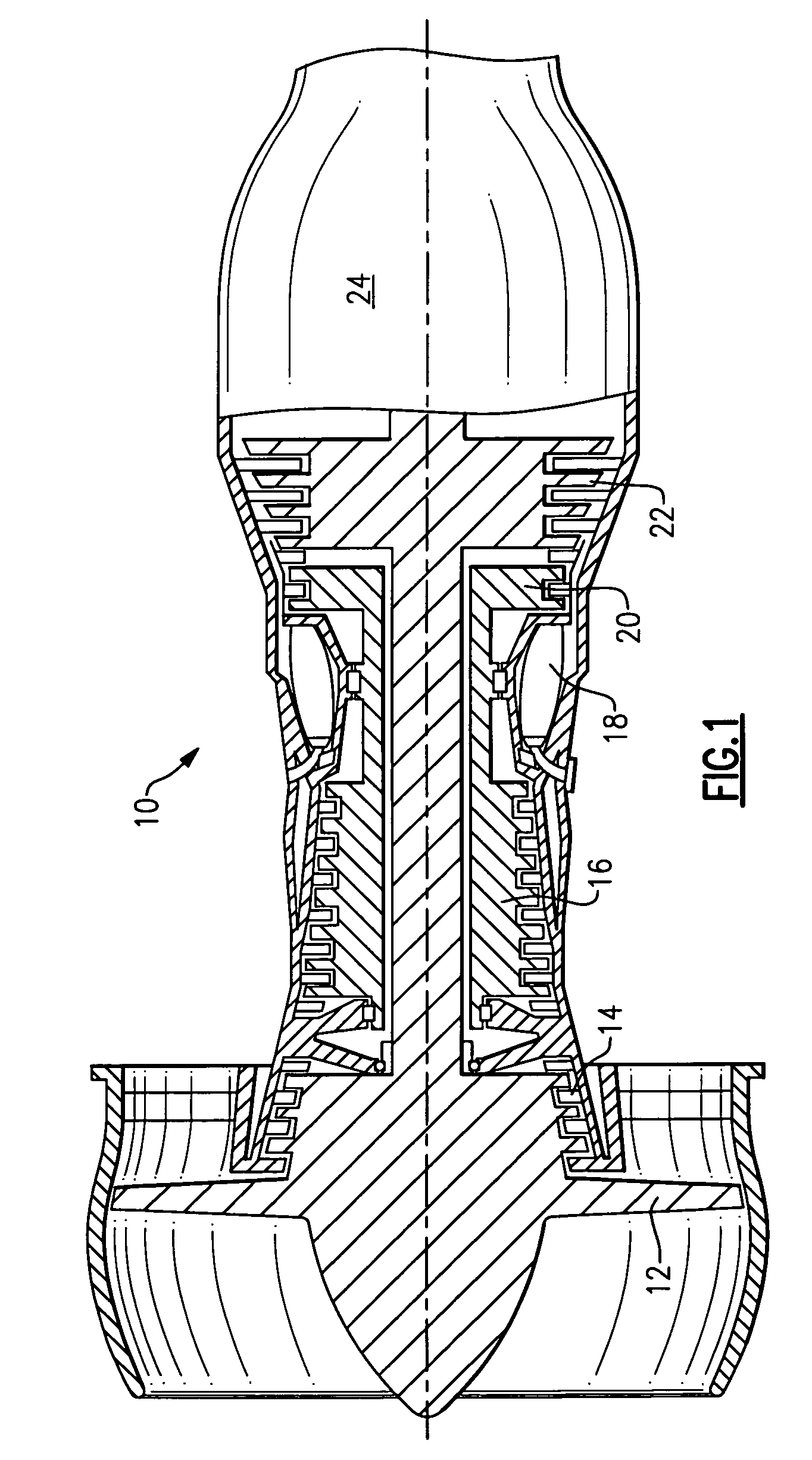
[0022]FIG. 1 is a schematic view of a turbine engine 10. Air is pulled into the turbine engine 10 by a fan 12 and flows through a low pressure compressor 14 and a high pressure compressor 16. Fuel is mixed with the air and combustion occurs within the combustor 18. Exhaust from combustion flows through a high pressure turbine 20 and a low pressure turbine 22 prior to leaving the engine through the exhaust nozzle 24.

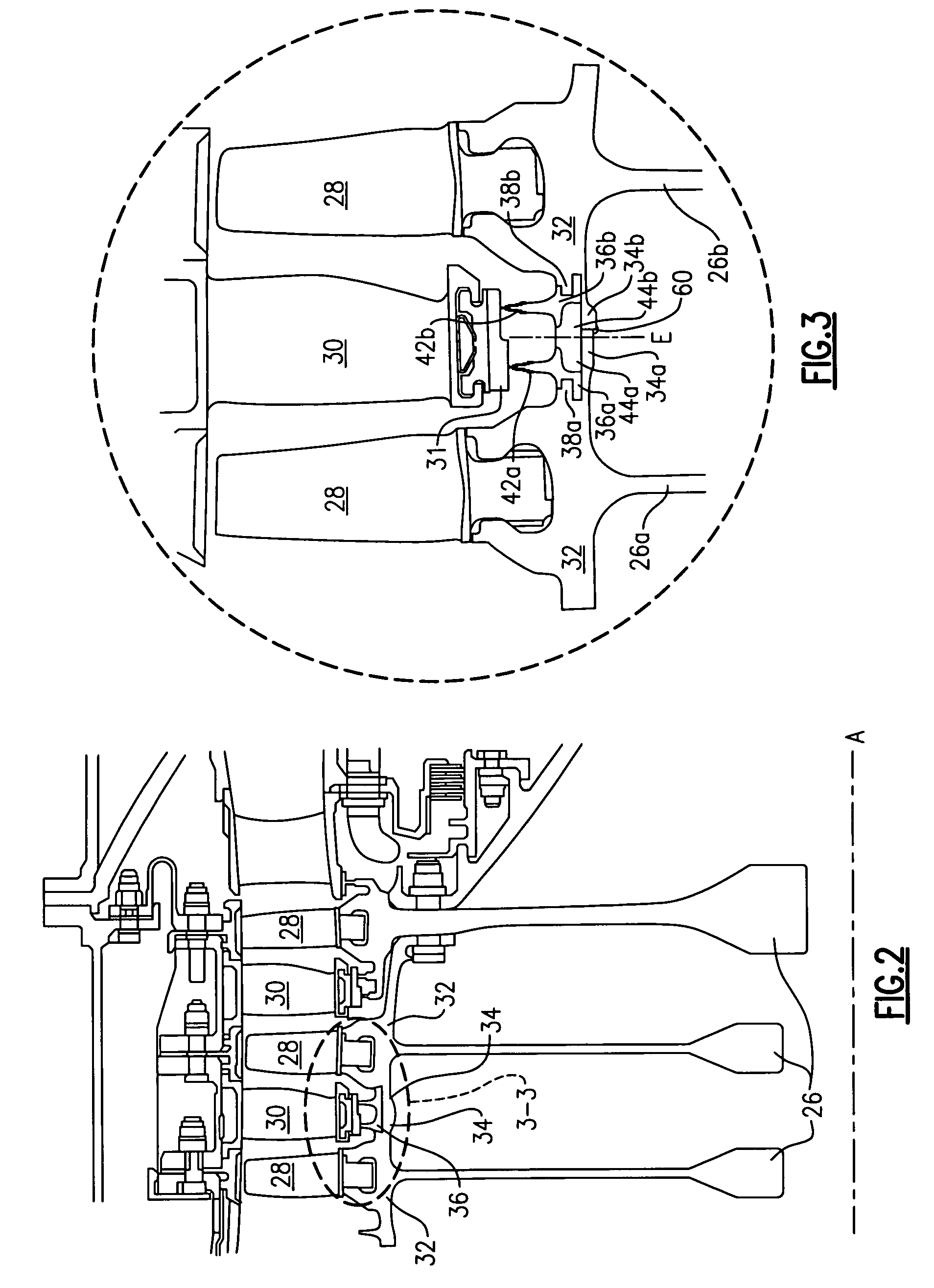
[0023]FIG. 2 illustrates a portion of a cross-section of a typical compressor including multiple disks 26 defining a compressor rotor. Each disk 26 rotates about an axis A located along the centerline of the turbine engine 10. A plurality of rotor blades 28 are mounted about the circumference of each of the disks 26. A plurality of stator vanes 30 extend between the rotor blades 28 of axially adjacent disks 26, as shown.

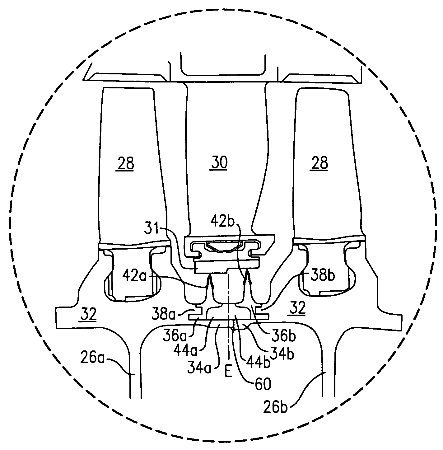
[0024]Each disk 26 includes a disk rim 32. The disk rim 32 supports the rotor blades 28. A backbone 34 extends from each disk rim 32. A plurality of knife...


PUM

PropertyMeasurementUnit
circumferenceaaaaaaaaaa
pressureaaaaaaaaaa
compressiveaaaaaaaaaa

Abstract

A compressor for a turbine engine includes multiple compressor disks having rotor blades mounted about the circumference of each of the disks. A plurality of stator vanes extend between the rotor blades of axially adjacent disks. A knife edge seal segment is supported by each disk backbone extending from the disks and contacts the stator vanes to restrict leakage of compressed air from between the stator vane and the compressor rotor to limit the recirculation of air. Retaining flanges extend from each disk rim to retain the knife edge seal segments to the disk backbone and spacer bridges integral to the knife edge seal segments prevent axial movement of the knife edge seal segments. A plurality of lock assemblies are spaced about the circumference of the disk backbone to prevent circumferential shifting and rotating of the knife edge seal segments during operation.

Description

BACKGROUND OF THE INVENTION[0001]The invention generally relates to an arrangement for loading and retaining knife edge seals within a compressor.[0002]Turbine engines include high and low pressure compressors to provide compressed air for combustion within the engine. Each compressor typically includes multiple rotor disks. Stator vanes extend between each rotor disk along a compressor axis. Knife edge seals are formed integrally into each rotor disk to contact the stator vanes. The seals restrict leakage of compressed air from between the stator vanes and the rotor disks to limit the recirculation of air within the compressor.[0003]During operation of the compressor the rotor disk is repeatedly heated and cooled, resulting in compressive and tensile hoop stresses on the outer portion of the disk, including the knife edge seals. This cyclic loading from the thermal cycles fatigue the disk and knife edge seals. Any areas of concentrated stress are prone to cracking as a result of th...

Claims


Application Information

Patent Timeline
Patent Type & Authority Patents(United States)
IPC IPC(8): F01D11/00
CPCF01D11/001F04D29/164Y10T29/49236Y10T29/4932Y10T29/49238
Inventor TRAN, TUYPICKENS, JOHN T.
Owner RTX CORP
Why Eureka
Try Eureka