Directional gamma ray probe

a gamma ray probe and gamma ray technology, applied in the field of directional radiation detectors, can solve the problems of multiple fragments of radioactive material scattered over an area, requiring rapid remediation, isolation and identification of radioactive material by first responders, and achieve the effect of accurately facilitating the localization of the emitter

Inactive Publication Date: 2008-12-30
HER MAJESTY THE QUEEN AS REPRESENTED BY THE MINIST OF NAT DEFENCE OF HER MAJESTYS CANADIAN GOVERNMENT
View PDF10 Cites 11 Cited by
  • Summary
  • Abstract
  • Description
  • Claims
  • Application Information

AI Technical Summary

Benefits of technology

[0006]It is an object of the present invention to provide a portable radiation detector which indicates the direction of incident gamma radiation from an emitter by angle to accurately facilitate the localization of that emitter.

Problems solved by technology

The detonation of a radiological dispersal device (a dirty bomb), the deliberate damaging of a radioisotope production facility or indeed many other terrorist scenarios could result in multiple fragments of radioactive material being strewn over an area in relatively close proximity to one another, requiring rapid remediation.
The presence of multiple radioactive sources in an area poses a problem in the isolation and identification of the radioactive material by first responders.
First responders have difficulty localizing radiation sources in a multi-source environment due to the isotropic nature of most conventional radiation detection equipment, thus prolonging the time spent in potentially high dose-rate areas resulting in an increased dose received by the first responders.
Current radiation detection equipment is isotropic in response, thus providing little directional information to the user.
The current solutions mentioned above have serious limitations.
The use of pancake probes to detect the associated beta emissions (very close to the ground or source) will result in even more gamma dose to the responders; the use of collimated detectors will demand an unacceptable mass increase—i.e. the detector becomes to heavy to be considered portable; and the use of electronic methods, such as modified composite scintillator assembly systems (such as a phosphor sandwich), are not suitable at higher energies owing to particle range considerations.
Monte Carlo simulations to investigate the feasibility of using a phosphor sandwich design clearly demonstrated their poor directional response and poor spectroscopic identification ability.
These systems are also typically large and bulky, currently transportable but not man-portable.

Method used


Image

  • Directional gamma ray probe
  • Directional gamma ray probe
  • Directional gamma ray probe

Examples


Embodiment Construction

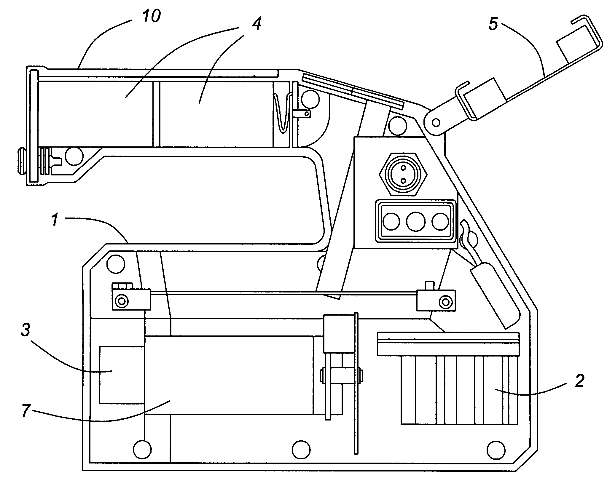
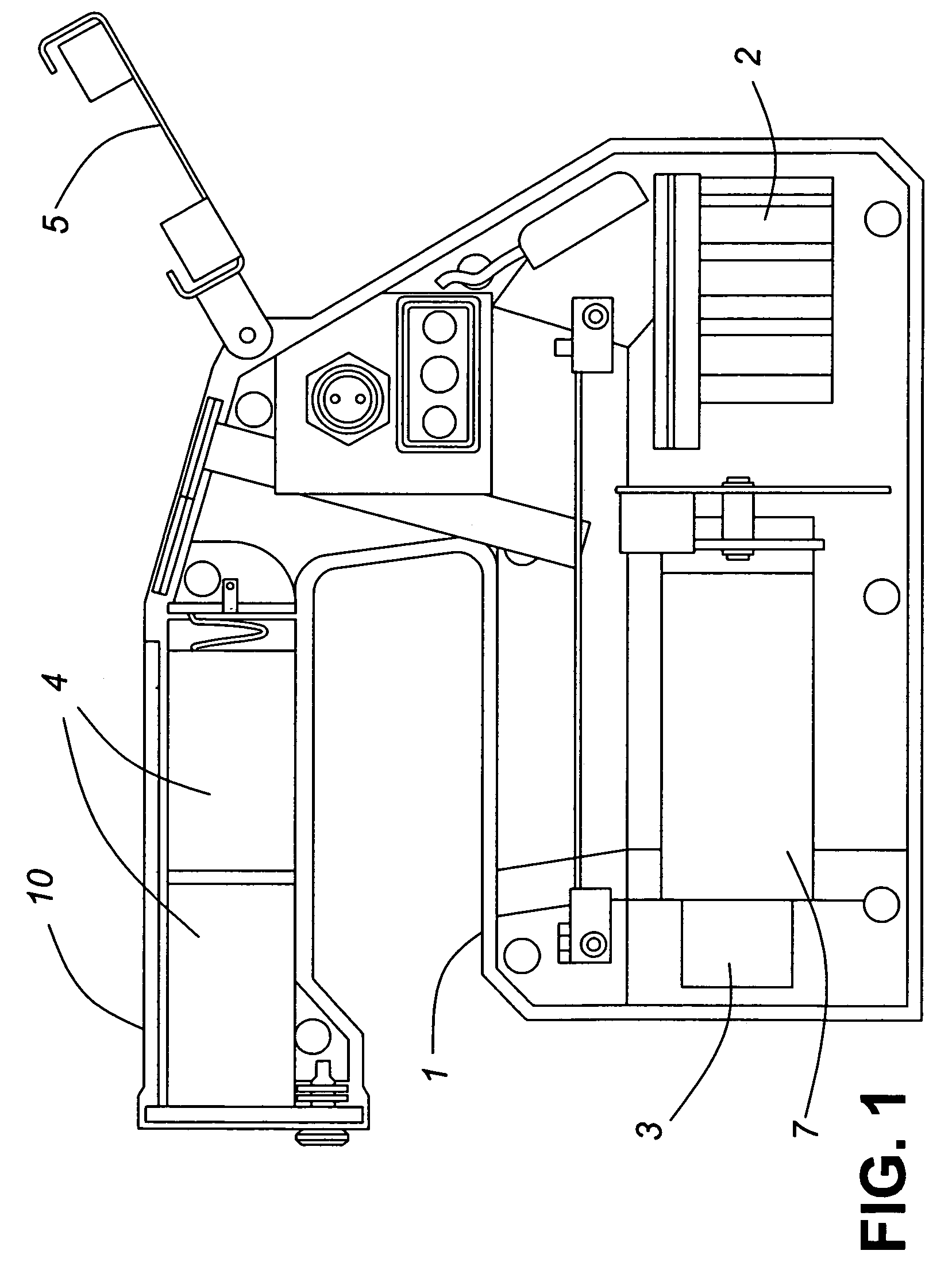
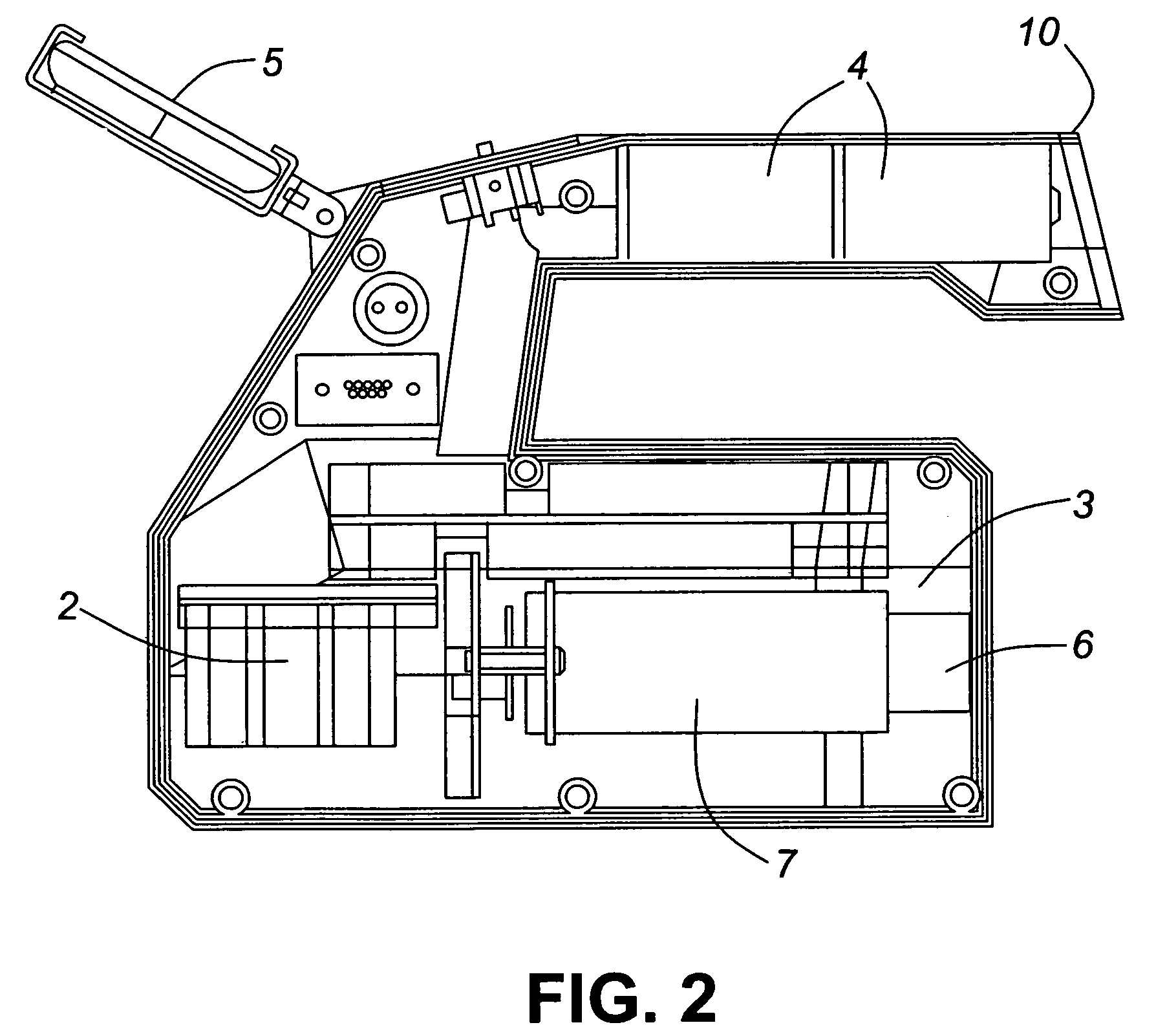
[0015]The detonation of a radiological dispersal device (a dirty bomb), the deliberate damaging of a radioisotope production facility or indeed many other terrorist scenarios could result in multiple fragments of radioactive material being strewn over an area in relatively close proximity to one another, requiring rapid remediation. The presence of multiple radioactive sources in an area poses a problem in the isolation and identification of the radioactive material by first responders. First responders have difficulty localizing radiation sources in a multi-source environment due to the isotropic nature of most conventional radiation detection equipment, prolonging the time spent in potentially high dose-rate areas leading to an increased dose received by the first responders. Current radiation detection equipment is isotropic in response, thus providing little directional information to the user. Even in the case of a single isolated radioactive source, the isotropic detector resp...


PUM


Abstract

A portable directional gamma ray radiation detector having a plurality of gamma ray radiation detectors separated by lead shielding arranged in an enclosure. Outputs from the detectors are applied to a signal processor to determine the location of a gamma ray emitter, and the signal processor is connected to a display device on the detector that indicates the direction to the gamma ray emitter.

Description

FIELD OF THE INVENTION[0001]The present invention relates to a radiation detector and, in particular to a portable directional radiation detector which indicates the direction of incident gamma radiation sources by angle and, consequently, facilitates the location of gamma radiation emitters.BACKGROUND OF THE INVENTION[0002]The detonation of a radiological dispersal device (a dirty bomb), the deliberate damaging of a radioisotope production facility or indeed many other terrorist scenarios could result in multiple fragments of radioactive material being strewn over an area in relatively close proximity to one another, requiring rapid remediation. The presence of multiple radioactive sources in an area poses a problem in the isolation and identification of the radioactive material by first responders. First responders have difficulty localizing radiation sources in a multi-source environment due to the isotropic nature of most conventional radiation detection equipment, thus prolongi...

Claims


Application Information

Patent Timeline
Patent Type & Authority Patents(United States)
IPC IPC(8): G01T1/16
CPCG01T1/169G01T1/2907
Inventor LARSSON, CAREY L.ING, HARRYDJEFFAL, SALAHANDREWS, HUGH R.ZHANG, MING
Owner HER MAJESTY THE QUEEN AS REPRESENTED BY THE MINIST OF NAT DEFENCE OF HER MAJESTYS CANADIAN GOVERNMENT
Why Eureka
Try Eureka