Coaxial cable having high radiation efficiency

a radiation efficiency and coaxial cable technology, applied in the direction of power cables, cables, insulated conductors, etc., can solve the problems of relatively lesser bandwidth and directionality capabilities, series radiation hazards, and use in proximity to military personnel, and achieve high efficiency and high efficiency.

Inactive Publication Date: 2008-12-30
HRL LAB
View PDF6 Cites 17 Cited by
  • Summary
  • Abstract
  • Description
  • Claims
  • Application Information

AI Technical Summary

Problems solved by technology

However, the phase velocity of the monofilar mode is just slightly slower than the speed of light, which means that it is only loosely bound to the cable, and extends a significant distance into free space.
Thus, traditional helical wound leaky cable antennas work over long distances because of the constant flow of energy between these two weakly coupled modes, with the monofilar mode gradually leaking power into the surrounding space.
Use in proximity to military personnel has raised series radiation hazard issues.
Prototypes described therein also exhibit signal distribution patterns sometimes having one or more null regions, thus exhibiting a relatively lesser operational efficiency.
Another problem is that military specifications define specific signal polarizations for particular applications.
However, for such applications, problems related to signal transmission—e.g., bandwidth and directionality capabilities, field effects due to proximity of a human body, and the like—and to wearability—e.g., disguisability, weight and flexibility, robustness, radiation hazards protection, and the like—must be accounted for in the design.

Method used


Image

  • Coaxial cable having high radiation efficiency
  • Coaxial cable having high radiation efficiency
  • Coaxial cable having high radiation efficiency

Examples


Embodiment Construction

[0034]The present invention discloses mechanisms for significantly boosting the rate of conversion between bifilar and monofilar modes in radiating coaxial cable transmission lines. In an implementation as a leaky cable antenna, the present invention has been found to be highly efficient when compared to known manner leaky cable antennas. The mode conversion is a factor which may be measured in coupling / meter for EM waveband signal coupling attenuation rate or growth rate.

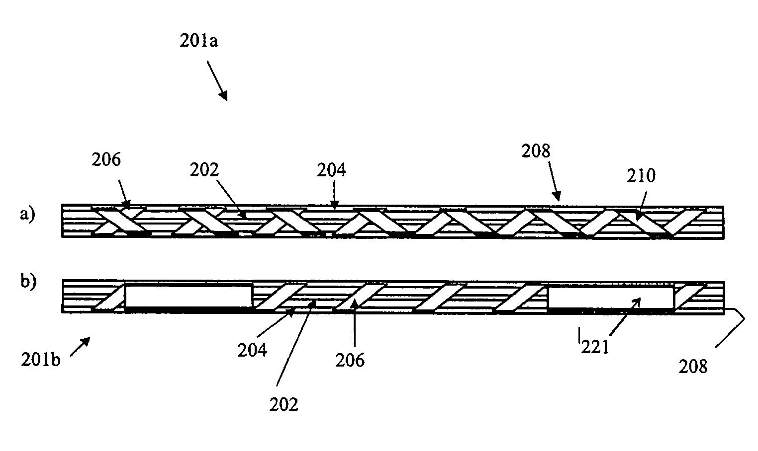
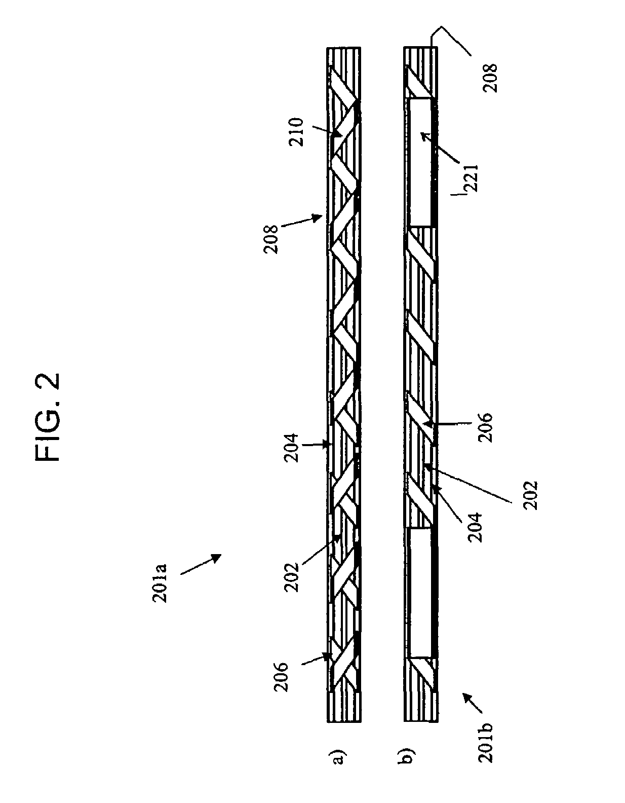
[0035]FIG. 2 shows two exemplary embodiments of mode conversion structures in longitudinal section elevation views. Beginning with FIG. 2 section a), there is shown a first exemplary embodiment of a leaky cable antenna 201a in accordance with the present invention.

[0036]The antenna 201a structure includes a center conductor 202, an inner insulator 204, a helical wound outer conductor 206, and an outer-insulator 208, all generally fabricated in a known manner. Conductive and dielectric materials may be used in accor...


PUM


Abstract

A radiating coaxial cable transmission line that may be used as an antenna. Mechanisms are incorporated for boosting the rate of conversion of bifilar mode to monofilar mode.

Description

CROSS-REFERENCE TO RELATED APPLICATIONS[0001]Not applicable.STATEMENT REGARDING FEDERALLY SPONSORED RESEARCH OR DEVELOPMENT[0002]Not applicable.REFERENCE TO AN APPENDIX[0003]Not applicable.FIELD[0004]The technology described herein is generally related to the field of coaxial cables, more specifically to radiating coaxial cable transmission lines, and particularly to types used as antennas.BACKGROUND[0005]It is known to use a radiating coaxial cable transmission line, also commonly referred to as a “leaky wave coaxial cable” or simply a “leaky cable,” as an antenna. Long line leaky cable antennas are useful for communication applications where a point source antenna is inadequate—e.g., in tunnels, mines, along roadways, or the like. Standard coaxial cables are modified to have slots, loose braids, or helical shields designed so that communication signals leak out over long distances, e.g., several miles or kilometers. Fundamentals of known manner radiating coaxial cable technology a...

Claims


Application Information

Patent Timeline
Patent Type & Authority Patents(United States)
IPC IPC(8): H01Q1/36
CPCH01Q1/273H01Q13/203
Inventor HSU, TSUNG-YUANSIEVENPIPER, DANIEL F.
Owner HRL LAB
Why Eureka
Try Eureka