X-ray diffraction apparatus

a diffraction apparatus and diffraction ray technology, applied in the direction of material analysis using radiation diffraction, instruments, measurement devices, etc., can solve the problems of reducing the resolution, increasing the background level, and not being able to perform high reliability, etc., and achieve the effect of favorable optical conditions

Inactive Publication Date: 2008-12-30
RIGAKU CORP
View PDF4 Cites 11 Cited by
  • Summary
  • Abstract
  • Description
  • Claims
  • Application Information

AI Technical Summary

Benefits of technology

[0021]The present invention has been made in view of the above problems, and an object thereof is to provide an X-ray diffraction apparatus capable of obtaining a high resolution in the high angle region with respect to diffraction angle 2θ and simplifying control of the slit width.

Problems solved by technology

However, although the intensity of the diffracted X-ray is increased in the high angle region, resolution is decreased due to widening of the X-ray irradiation field.
Thus, the measurement that needs to be performed under the condition that the amount of X-ray is kept constant, (such as refined analysis, in general), cannot be performed with high reliability.
However, absence of the scattering slit on the receiving side may increase the background level.
However, the X-ray diffraction apparatus according to the technique disclosed in Japanese Patent Application Laid-Open Publication No. 2000-55837 could not obtain desired high resolution on the high angle side.
Recently, it was found that a slight difference in the crystal structure of TiO2 (titania), which is used as a photocatalyst, leads to a large difference in its photocatalysis function.
However, the X-ray diffraction apparatuses disclosed in Japanese Patent Publication No. 53-28222, Japanese Utility Model Publication No. 3-55890, and Japanese Patent Laid-Open Publication No. 2000-55837 could not obtain a satisfactory resolution in the high angle region with respect to diffraction angle 2θ.
Actually, however, it was impossible to perform measurement with a high resolution in the high angle region due to absence of the scattering slit for restricting the X-ray width on the sample on the receiving side.
Further, the apparatus disclosed in Japanese Patent Laid-Open Publication No. 2000-55837 adopts a technique that widens the slit width of the divergence slit on the low angle side relative to a predetermined X-ray incident angle θa while keeps the slit width of the divergence slit on the high angle side relative to the predetermined angle θa, which complicates the slit width control of the divergence slit, resulting in an increase in cost.

Method used


Image

  • X-ray diffraction apparatus
  • X-ray diffraction apparatus
  • X-ray diffraction apparatus

Examples


Embodiment Construction

[0048]An X-ray apparatus according to the present invention will be described based on a preferred embodiment. It should be noted that the present invention is not limited to the following embodiment. Although the following description is made with the accompanying drawings, there is a case where components in the drawings may be shown at a different scale from actual ones for easy understanding of their feature points.

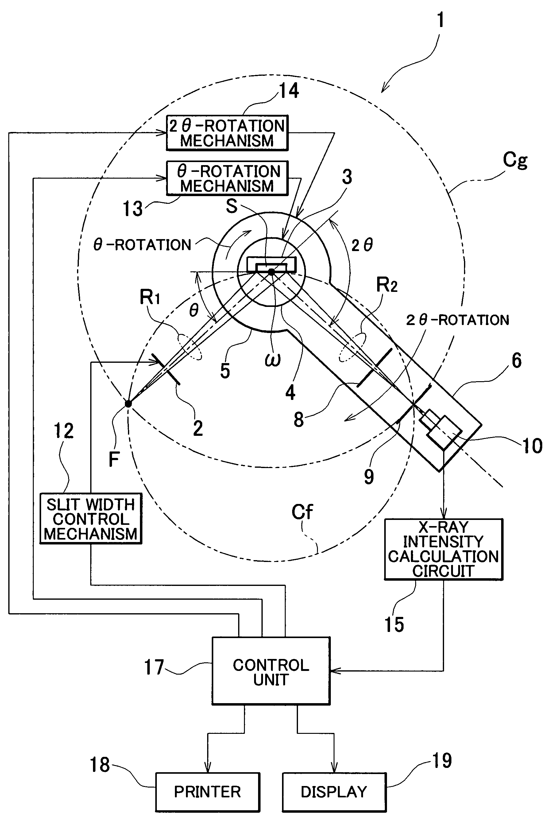
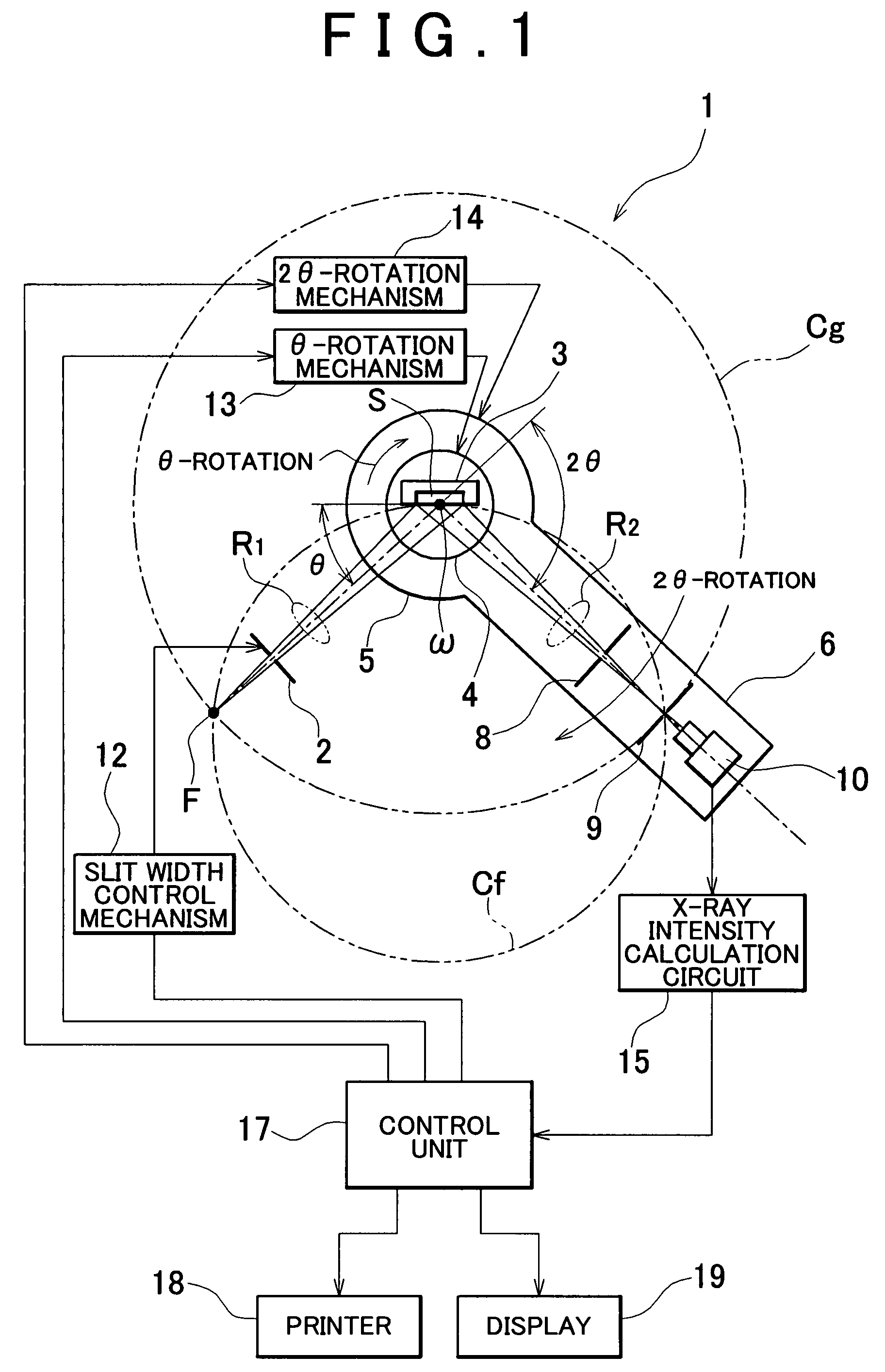
[0049]FIG. 1 shows an embodiment of an X-ray diffraction apparatus according to the present invention. An X-ray diffraction apparatus 1 shown in FIG. 1 has an X-ray source F for generating X-ray, a divergence slit 2 for restricting divergence of X-ray, a θ-rotation table 4 for supporting a sample holder 3, a 2θ-rotation table 5 coaxially arranged with the θ-rotation table 4, and a detector arm 6 extending from the 2θ-rotation table 5. The X-ray source F and the divergence slit 2 are fixed so as not to be moved. A sample S which is an object to be measured is filled in...


PUM

PropertyMeasurementUnit
divergence angleaaaaaaaaaa
aaaaaaaaaa

Abstract

Disclosed is an X-ray apparatus having an X-ray source, an X-ray detector, a divergence slit, and a scattering slit. The incident angle θ of X-ray to be irradiated on a sample is changed at a predetermined angular speed at measurement time and diffracted X-ray detection angle 2θ at which the X-ray detector detects X-ray is changed in the opposite direction to the θ-direction at an angular speed double that of the X-ray incident angle θ. The slit width of the divergence slit is changed such that the X-ray irradiation width always coincides with the sample width while the slit width of the scattering slit is retained at a constant value. The width of X-ray received by the X-ray detector is restricted by the narrower one of the divergence slit and the scattering slit. The resolution in the high angle region can be kept at a high level.

Description

BACKGROUND OF THE INVENTION[0001]1. Field of the Invention[0002]The present invention relates to an X-ray diffraction apparatus that restricts X-ray on the incident side by a divergence slit and restricts X-ray on the receiving side by a scattering slit.[0003]2. Description of the Related Art[0004]There is widely known an X-ray diffraction apparatus for analyzing the crystal structure of a substance. Some X-ray diffraction apparatus are based on the principle of a focusing method. This principle is sometimes called “Bragg-Brentano focusing method”. As an X-ray diffraction apparatus using a focusing optical system, an apparatus shown in FIG. 7 is known. In this apparatus, an X-ray source F, a sample S, and a receiving slit RS are mounted on a focusing circle Cf. X-ray generated from the X-ray source F is incident on the sample S while its divergence is restricted by a divergence slit DS. When the diffraction condition of Bragg is satisfied, X-ray is diffracted by the sample S, and di...

Claims


Application Information

Patent Timeline
Patent Type & Authority Patents(United States)
IPC IPC(8): G01N23/20
CPCG01N23/20
Inventor DOSHO, AKIHIDE
Owner RIGAKU CORP
Why Eureka
Try Eureka