Insensitive munitions warhead explosive venting system

a venting system and insensitive technology, applied in the field of ordnance casings, can solve the problems of military system damage, explosion of bombs, and many weapons developed in the past did not take into account all,

Active Publication Date: 2009-01-06
SEC OF THE NAVY AS REPRESENTED BY THE UNTITED STATES OF AMERICA
View PDF19 Cites 20 Cited by
  • Summary
  • Abstract
  • Description
  • Claims
  • Application Information

AI Technical Summary

Benefits of technology

[0006]The venting system according to the present invention preferably further includes an insert ring mounted on an outer surface of the failure mechanism. The insert ring is typically formed of a durable material such as steel to protect the failure mechanism from being damaged and to provide shielding from external electromagnetic fields that could detonate the explosive and prevent tampering with the explosive.
[0008]An adhesive may be placed between adjacent portions of the failure mechanism and the base plug and between adjacent portions of the insert ring and the base plug to provide additional sealing and retaining capability.

Problems solved by technology

Many weapons developed in the past did not take into account all of the severe environments that a weapon may encounter during its lifecycle.
These environments may include fast burning, excessive heat, impact with bullets and fragments, etc.
When such warheads are exposed to a fire, such as could occur on the deck of an aircraft carrier, there is sufficient heat transfer to the explosive material inside of the bomb casing to cause an explosion of the bomb.
This could cause significant damage to military systems and serious injury or even death to individuals in proximity to the bomb.
Previous attempts to produce insensitive munitions neither provide a cover to prevent tampering nor cover all hazards of electromagnetic radiation to ordnance and issues related to electrostatic discharge.
Prior art devices also fail to provide sealing for high external case pressures that can exist when ordnance is submerged in water.

Method used


Image

  • Insensitive munitions warhead explosive venting system
  • Insensitive munitions warhead explosive venting system
  • Insensitive munitions warhead explosive venting system

Examples


Embodiment Construction

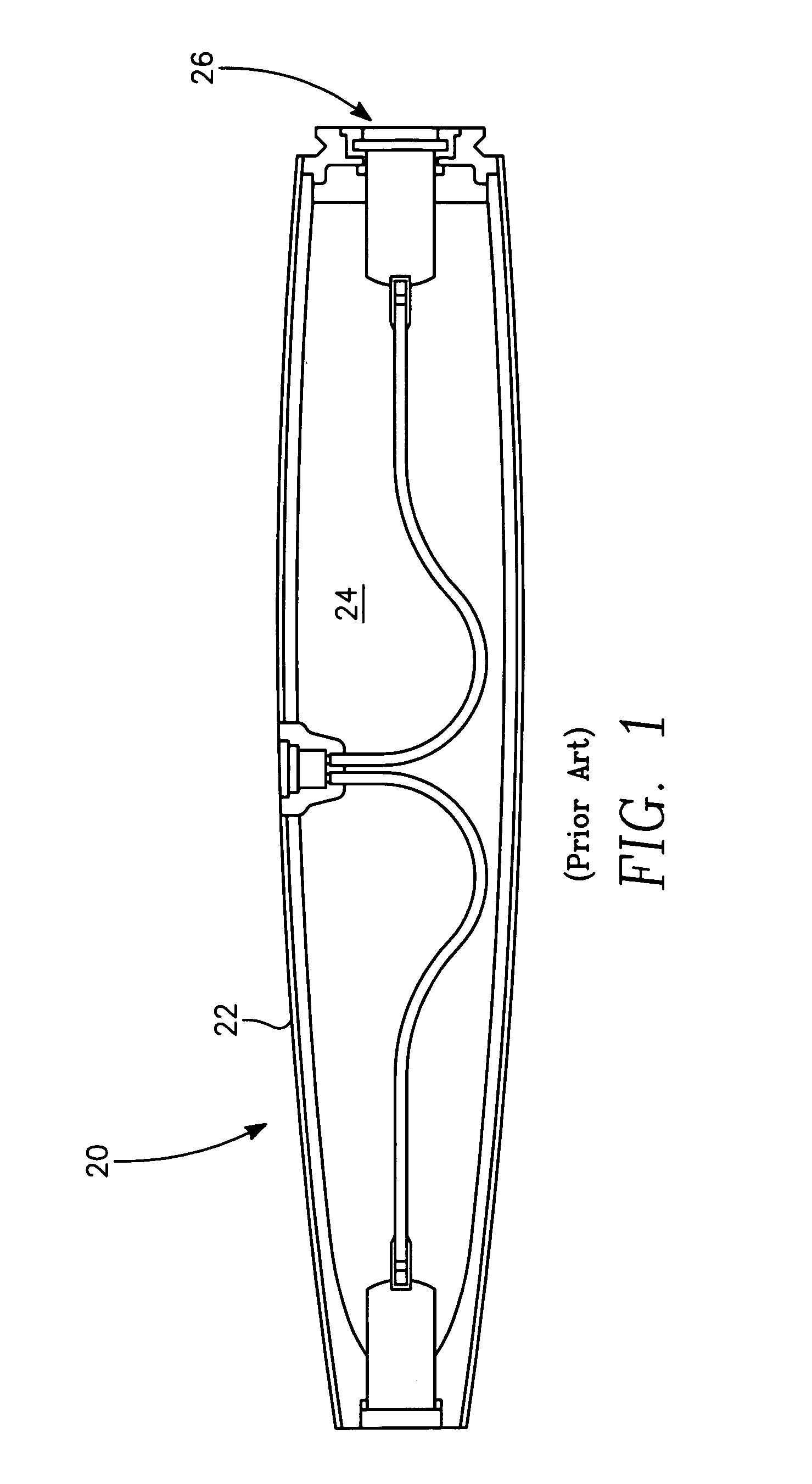
[0024]Referring to FIG. 1 a bomb 20 has an unvented casing 22 that contains an explosive material 24. The casing 22 includes a base plug 26 that forms an airtight seal of the explosive material, which is typical of prior art bomb casings.

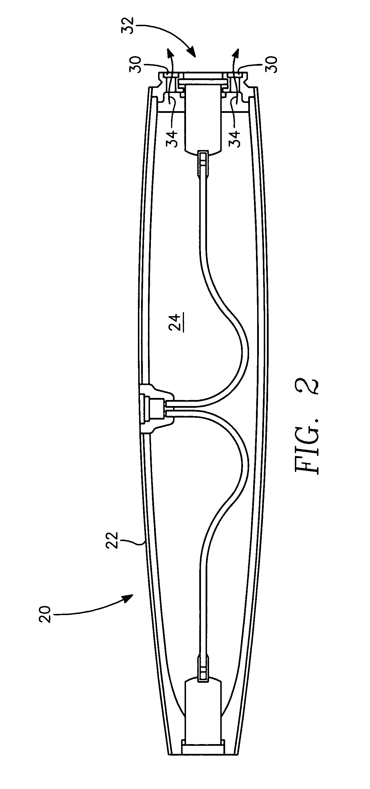
[0025]FIG. 2 illustrates the current configuration for a bomb 20 which has a plurality of venting ports 30 located within a base plug 32 of the bomb 20. The base plug 32 preferably is formed generally as a cylindrical steel plate. When heat is transferred to the explosive material 24, the venting ports 30 within the base plug 32 allow for a controlled burn of the explosive material 24 within the bomb casing 22 instead of exploding. The venting of the explosive material 24 occurs in the direction indicated by the arrows 34 shown in FIG. 2.

[0026]FIG. 3 is an enlarged cross sectional view of the base plug 32 showing the venting ports 30. FIG. 4 is an end elevation view illustrating the base plug 32. FIG. 4 shows the base plug 32 including six venting p...


PUM


Abstract

A venting system for a casing containing an explosive material includes a base plug having one or more venting ports. A ring-shaped failure mechanism mounted to the base plug seals the venting ports. The failure mechanism has a selected melting temperature such that raising the temperature of the failure mechanism to its melting temperature causes the failure mechanism to unseal the venting port to allow controlled burning of the explosive material. An insert ring formed of a durable material to protect the failure mechanism from being damaged may be mounted on an outer surface of the failure mechanism. An adhesive may be used to seal gaps between the failure mechanism, the insert ring and the base plug. The failure mechanism may have a peripheral tab formed to fit within a corresponding groove in the base plug to mount the failure mechanism securely to the base plug.

Description

BACKGROUND OF THE INVENTION[0001]This invention relates generally to ordnance casings and particularly to a bomb casing having a vented base plug for providing a controlled burn of explosive material in the bomb casing to prevent an explosion from occurring in the event that the bomb casing is exposed to a high temperature environment.[0002]Insensitive munitions have become very important in national defense technology. Many weapons developed in the past did not take into account all of the severe environments that a weapon may encounter during its lifecycle. These environments may include fast burning, excessive heat, impact with bullets and fragments, etc. Many current warhead designs have a case and a closure that has no venting ports or stress risers to allow the explosive to burn or relieve internal pressure resulting from severe heating environments. When such warheads are exposed to a fire, such as could occur on the deck of an aircraft carrier, there is sufficient heat trans...

Claims


Application Information

Patent Timeline
Patent Type & Authority Patents(United States)
IPC IPC(8): F41A17/00
CPCF42B39/20
Inventor HAYS, BRIAN VANCEHARDT, LEEBURNETT, DONALD
Owner SEC OF THE NAVY AS REPRESENTED BY THE UNTITED STATES OF AMERICA
Why Eureka
Try Eureka