
Versatile engine muffling system

a muffler and muffler body technology, applied in the field of mufflers, can solve the problems of limiting engine performance, affecting the operation of the muffler, and the structure of the muffler is not good,

Inactive Publication Date: 2009-01-06
LOCKHEED MARTIN CORP
View PDF41 Cites 14 Cited by
  • Summary
  • Abstract
  • Description
  • Claims
  • Application Information

AI Technical Summary

Benefits of technology

[0013]Although conventional sound absorbing materials may be employed for sound attenuation, more non-conventional materials may also be employed. In one such embodiment, the sound absorbing material may include loose particulates such as ceramics, glass, or stones that move in response to engine exhaust sound wave levels and the combustible gases to create a Helmholtz chamber tuning effect.
[0016]According to still another embodiment, a method of absorbing engine noise includes providing an engine muffler having at least one sound attenuation chamber configured as a fluidic passageway, and further having sound absorbing material disposed within the fluidic passageway, such that together, the fluidic passageway and the acoustic absorbing material operate to form a tortuous path through a plenum chamber, and attaching the muffler to an engine exhaust such that the engine muffler self-tunes itself to provide a desired level of acoustic muffling associated with the engine.

Problems solved by technology

Such configurations however, produce a relatively high pressure drop, causing a back pressure at the exhaust of the engine, thus limiting engine performance.
Sound absorbing materials generally employed in dissipative mufflers tends to deteriorate because of the structure of the material and the high velocity and temperature of the exhaust.
While mufflers including a combination of some of the above structures are known in the art in a variety of configurations, such known muffler structures are generally disadvantageous in that they are not compact when employed in vertical exhaust applications.
Further, conventional muffler structures, although useful in reducing sounds of exhaust gasses from an engine, are incapable of self-tuning to meet the needs of multiple applications.

Method used


Image

  • Versatile engine muffling system
  • Versatile engine muffling system

Examples


Embodiment Construction

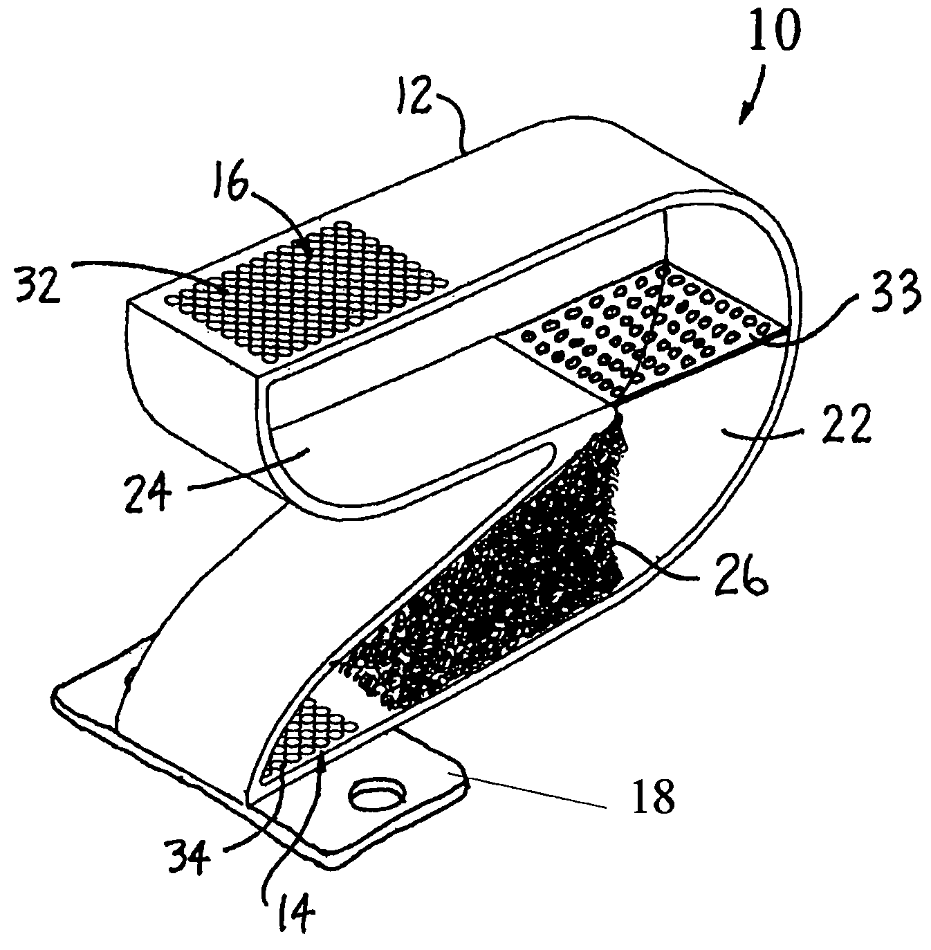
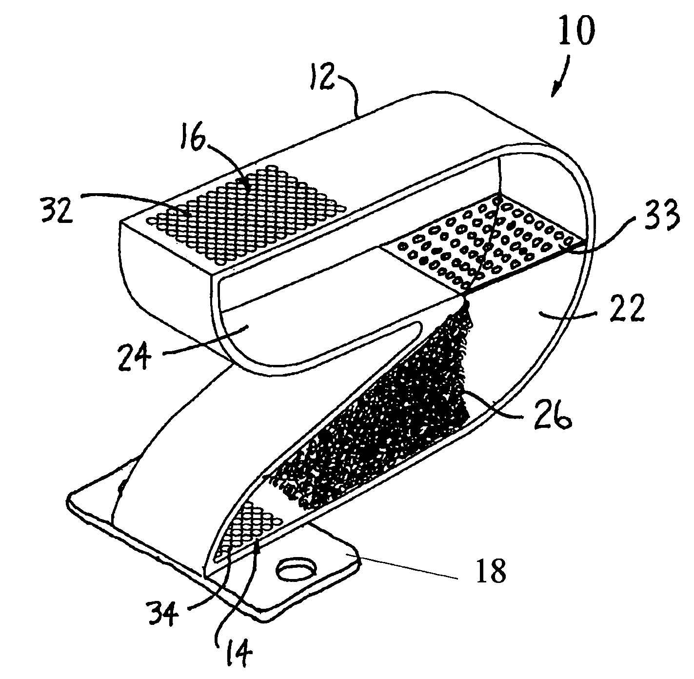
[0020]The FIGURE illustrates a perspective view of a muffler assembly 10 according to one embodiment of the invention. The muffler assembly 10 includes a muffler housing 12 with an inlet port 14 at the bottom of the assembly 10 and an exhaust (outlet) port 16 at the top of the muffler housing 12. An engine mounting bracket 18 for attaching the assembly 10 to an upward directed engine exhaust port is attached to the bottom of the muffler assembly 10. The muffler housing 12 has a folded s-shape to advantageously limit the overall assembly height upon attaching the muffler assembly 10 to certain types of aircraft engine exhaust ports. The muffler assembly 10 therefore provides acoustic muffling in applications having vertical space limitations.

[0021]A plurality of muffler chambers 22, 24 include sound absorbing materials 26 selectively disposed therein. The sound absorbing materials 26 may be disposed within any one or more of the chambers 22, 24 depending upon the specific application...


PUM


Abstract

An engine muffling system includes a Helmholtz tuning chamber to meet the changing acoustic muffling requirements associated with multiple applications. The engine muffling system in one embodiment includes at least one chamber configured as a plenum device, typically filled with an aggregate material or acoustic absorbing particulate material(s) in order to produce a tortuous path through the at least one chamber.

Description

BACKGROUND OF THE INVENTION[0001]1. Field of the Invention[0002]This invention relates generally to the field of engine muffling systems. More particularly, the invention relates to a muffler having a tortuous path through multiple chambers including a plenum chamber that operates as a Helmholtz tuning chamber.[0003]2. Description of the Prior Art[0004]Mufflers are employed in engine exhaust systems to limit the pressure levels of exhaust noise and to reduce sound levels of exhaust gasses emitted from an engine. Mufflers generally are classified as either reactive or dissipative.[0005]Reactive mufflers generally include a number of resonating chambers of different volumes and shapes connected together with pipes. Reactive mufflers may include flow-reversals or baffles. Such configurations however, produce a relatively high pressure drop, causing a back pressure at the exhaust of the engine, thus limiting engine performance.[0006]Dissipative mufflers generally include ducts or chambe...

Claims


Application Information

Patent Timeline
IPC IPC(8): F01N1/24F01N1/04F01N1/10F01N1/02F01N1/08
CPCF01N1/04F01N1/081F01N1/083F01N2470/02F01N2470/10F01N2490/08F01N2590/00
Inventor MONSON, ROBERT J.YAN, JIANHUAVAN DUSEN, CHARITY R.
Owner LOCKHEED MARTIN CORP
Learn More