Bifocal plastic lens

a plastic lens and bifocal technology, applied in the field of bifocal plastic lenses, can solve the problems of hard release in the molding process, hard handling of the molding step, and difficulty in respecting processing

Inactive Publication Date: 2009-01-06
ASAHI LITE OPTICAL
View PDF13 Cites 20 Cited by
  • Summary
  • Abstract
  • Description
  • Claims
  • Application Information

AI Technical Summary

Benefits of technology

[0006]In order to prevent a boundary surface between the small lens and the bench lens from being conspicuous in the lens, it is preferable that a thickness of a peripheral edge portion of the small lens on the boundary surface should be equal or almost equal to that of the bench lens (a thickness of the small lens itself is set to be almost zero). In the case in which a step is made on the boundary surface of the peripheral edge portion of the small lens, moreover, at least a part of the step can also be constituted by a curved surface. Alternatively, such a property as to reduce a reflected light for coloring, matting or antireflection may be given to a surface constituting the step of the upper edge portion in the small lens.

Problems solved by technology

A mold for molding the step is hard to handle because a step portion is easily broken, and is hard to release in a molding process.
Thus, there are many problems in respect of the processing.

Method used


Image

  • Bifocal plastic lens
  • Bifocal plastic lens
  • Bifocal plastic lens

Examples


example 1

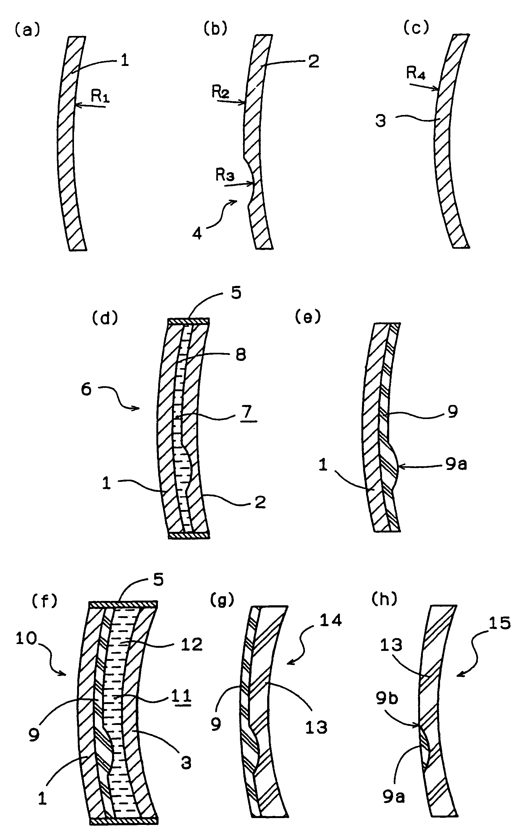
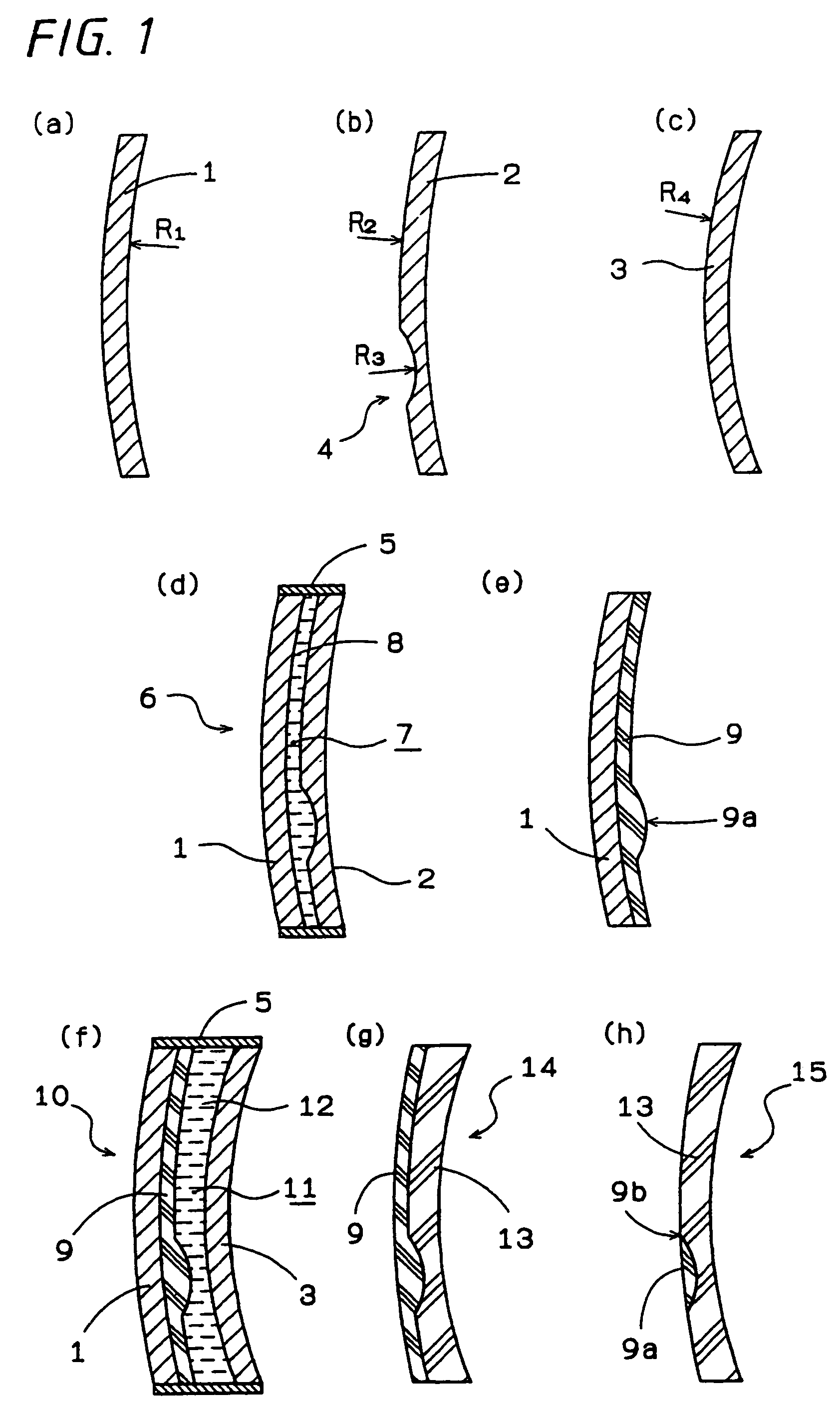
[0025]In FIG. 1, (a) and (b) are typical sectional views showing a pair of glass molds, which will be hereinafter simply referred to as sectional views. Moreover, a radius of curvature will be simply referred to as a curvature. Radius of curvatures R1 and R2 of molding surfaces of molds 1 and 2 give the same spherical surfaces. The surface having the radius of curvature R2 is provided with a concave portion 4 having a radius of curvature R3 which molds a small lens. FIG. 1(c) is a sectional view showing a mold 3 for molding a concave surface side of a compound lens which will be described below, and the molding surface has a radius of curvature of R4. FIG. 1(d) shows a shell 6 in which peripheral edge portions of the molds 1 and 2 are sealed with a tape 5. A first monomer 8 is cast into a cavity portion 7 in the shell and is heated and polymerized, and the mold 2 is released so that a preparatory lens member 9 including a small lens 9a shown in FIG. 1(e) is obtained. At this time, t...

example 2

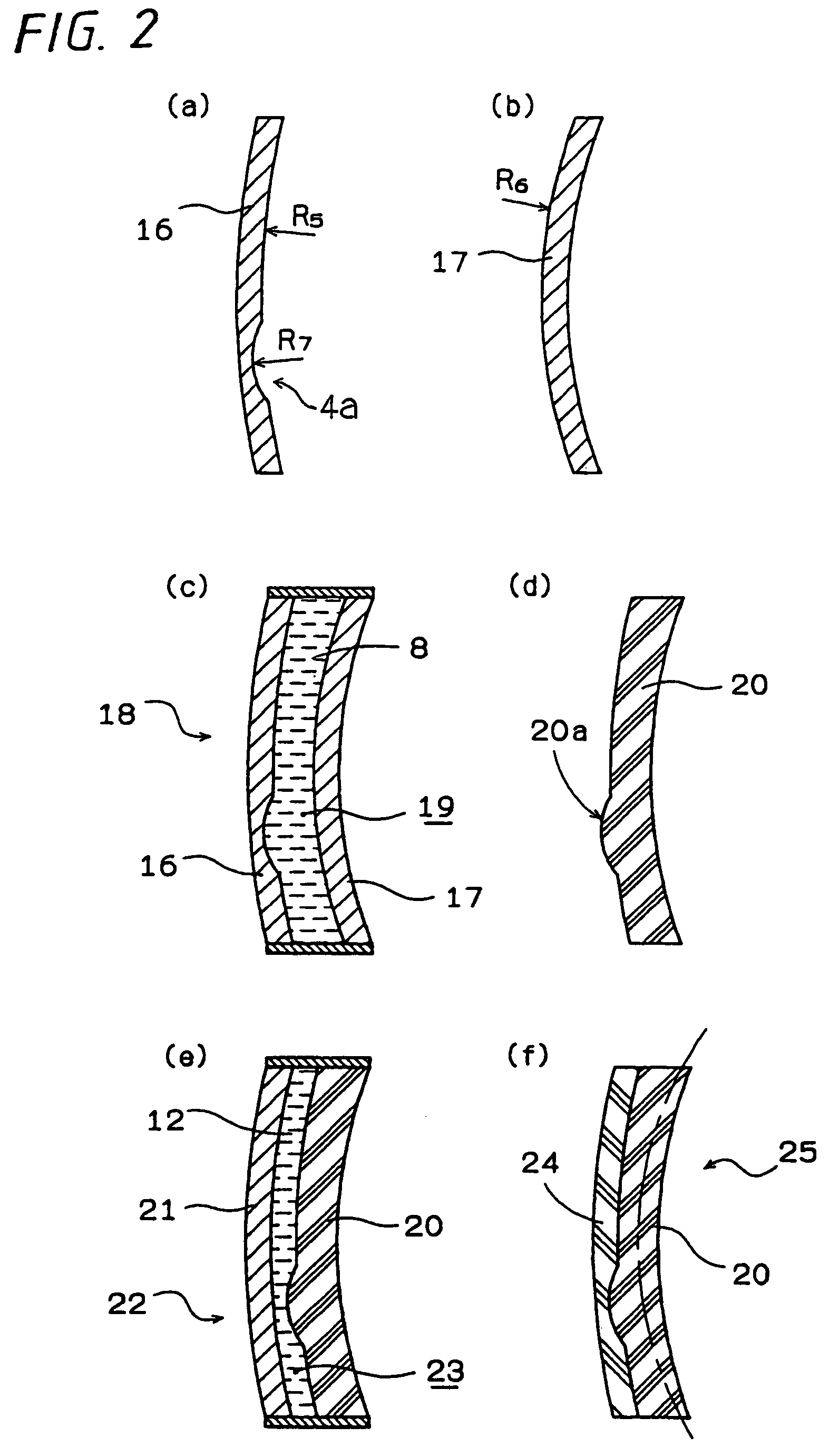
[0037]Next, description will be given to another embodiment of the compound lens. FIG. 2(a) shows a mold 16 in which a small lens molding surface is formed on a concave surface side. The concave surface side for molding a bench lens is a spherical surface having a radius of curvature of R5 and is provided with a concave portion 4a having a radius of curvature of R7 which molds a small lens. FIG. 2(b) shows a mold 17 forming a convex surface side of the bench lens, and the convex surface has a radius of curvature of R6. By using these molds, a peripheral edge portion is sealed with a tape 5 to create a shell 18, and the first monomer 8 is cast into a cavity portion 19 and is heated and polymerized and the molds are then released as shown in FIG. 2(c) so that a preparatory lens member 20 including a small lens 20a shown in FIG. 2(d) is obtained. As shown in FIG. 2(e), then, the preparatory member 20 and a mold 21 having radius of on a concave surface side which is equal to a radius of...

example 3

[0047]While the monomer having a high refractive index of 1.737 has been used in the example 1, description will be given to an example in which the same object can be achieved even if the refractive index is varied.

[0048]First monomer: MR-7 manufactured by MITSUI CHEMICALS, INC., Nd=1.660

[0049]Second monomer: CR-39 manufactured by PPG, Nd=1.498

[0050]In order to adhere these monomers, it is necessary to first polymerize and cure the second monomer and to then cast the first monomer. For the mold, a mold shown in FIG. 5 is used.

[0051]R5 (radius of curvature on a concave surface side of a mold 30)=332.5 (mm)

[0052]Radius of curvature on a concave surface side of a mold 33)=332.5 (mm)

[0053]R7=radius of curvature on an eye-facing side of a small lens

[0054]Table 3 shows a result obtained by calculating an additional power and the radius of curvature R7 on an eye-facing side of a small lens in the same manner as in the example 1. In comparison for an additional power of 3.00, R7 is 66.86. ...


PUM


Abstract

A bifocal plastic lens having a bench lens and a small lens with different refractive powers. The small lens not protruding above a surface of the bench lens, a boundary between the constituent lenses being difficult to see. The small lens may be provided on a preparatory lens member including the small lens. Alternatively, the preparatory lens member has a concave portion for a small lens molding surface. A resin having a higher refractive index than a resin constituting other portions of the lens is adhered to a surface provided with the small lens or the concave portion to be the small lens molding surface in the preparatory lens member, and is cured and integrated.

Description

TECHNICAL FIELD[0001]The present invention relates to a bifocal plastic lens.BACKGROUND ART[0002]In a bifocal plastic lens, generally, a bench lens and a small lens are constituted by the same resin. When the small lens is designed to have a smaller radius of curvature than the radius of curvature of the bench lens and a diameter of the small lens is increased in order to widen a near-sight view, an area of a far-sight section of the lens becomes small so that a field of far-sight view is reduced. When an upper part of the small lens is removed, a step is generated therein. Since the step is processed to be a plane, a boundary can be seen clearly. A mold for molding the step is hard to handle because a step portion is easily broken, and is hard to release in a molding process. Thus, there are many problems in respect of the processing. JP-A-49-88534 has described the prior art in which a step is not provided on an upper edge part of a small lens portion but the small lens portion is...

Claims


Application Information

Patent Timeline
Patent Type & Authority Patents(United States)
IPC IPC(8): G02C7/06
CPCG02C7/06B29D11/00028B29D11/0073
Inventor MATSUI, AKIHIDE
Owner ASAHI LITE OPTICAL
Why Eureka
Try Eureka