
Pumping system with progressive cavity pump

a cavity pump and progressive technology, applied in the direction of rotary piston engines, screws, engine lubrication, etc., can solve the problems of affecting the price, the weight of the device, the overdimension of the pin-jointed device, etc., and the correct operation of such a construction requires as little play as possibl

Inactive Publication Date: 2009-01-06
PCM TECH
View PDF10 Cites 21 Cited by
  • Summary
  • Abstract
  • Description
  • Claims
  • Application Information

AI Technical Summary

Benefits of technology

[0015]The object of the invention is to remedy, at least in part, the problems explained above and to propose a improved construction which gives better satisfaction to the various demands of the art, in particular in terms of structural simplicity, simplicity of assembly and disassembly, and cost.
[0019]Furthermore, the coupled devices are no longer drilled diametrically: they therefore retain their mechanical strength and it thus becomes possible to transmit significantly greater torque (typically around 30% greater). In other words, for the transmission of a given torque, the coupled devices can be made smaller, and therefore become less costly.
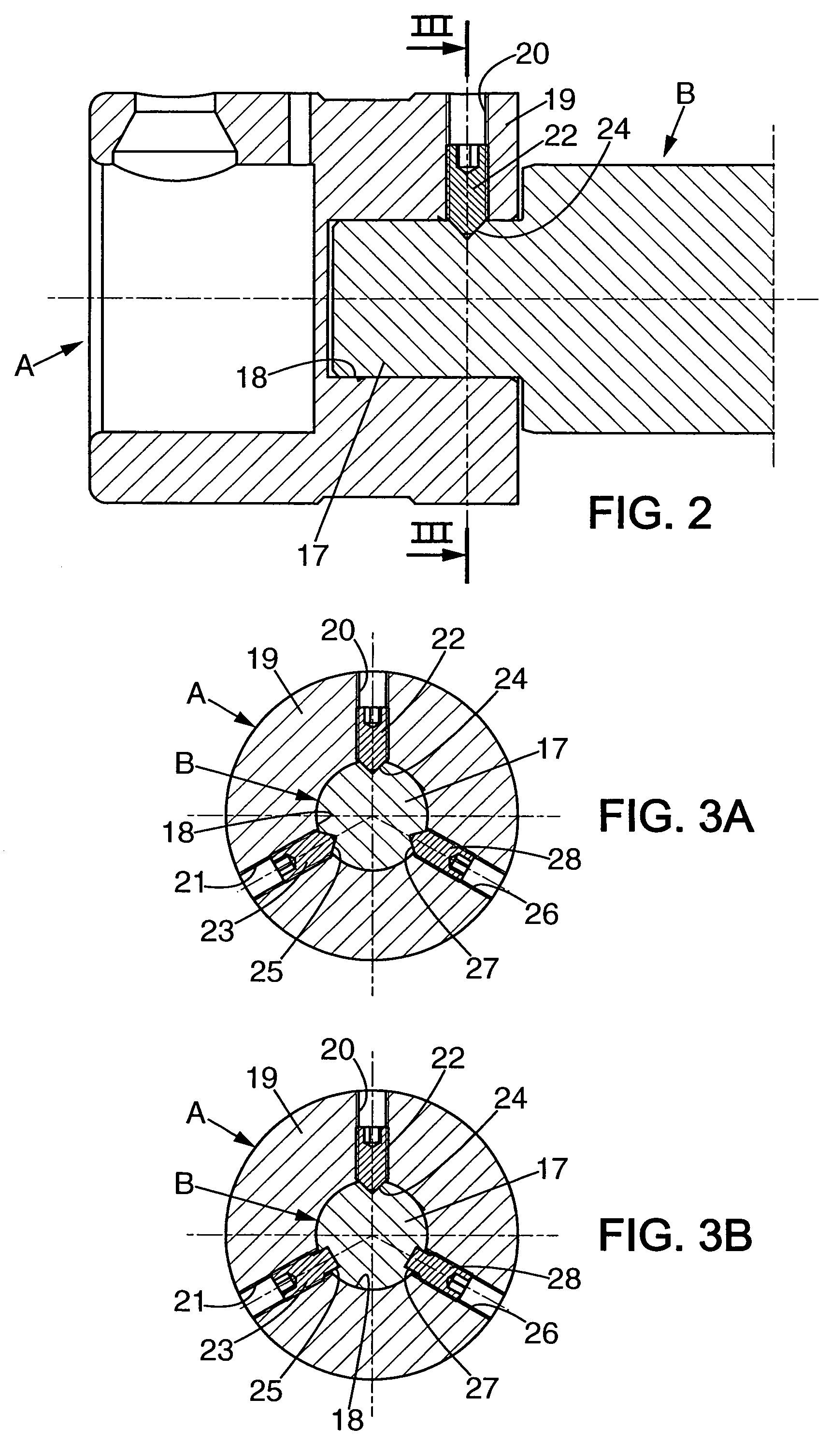
[0020]Preferably, the lateral wall of the axial housing of the female device includes three radial tapped drill holes distributed angularly and the axial stub of the male device includes three radial recesses distributed angularly and respectively located in line with said drill holes. Advantageously, then, the drill holes and respective recesses are distributed angularly in an equidistant manner. Such an assembly no longer requires precise fitting of the coupled devices relative to each other, which not only reduces the machining costs and facilitates assembly, but also eliminates the “fritting” effect mentioned above; the devices can therefore be dismantled more easily and more quickly.

Problems solved by technology

Firstly, all the units connected axially and rotation-wise are conventionally connected by means of pins, normally diametrical pins. Now, a pin joint requires the connected devices to be drilled diametrically. The presence of these diametrical drill holes significantly weakens the parts, such that the torques that can be transmitted are less than those that could be transmitted by solid parts. In other words, the transmission of a given torque requires the pin-jointed devices to be overdimensioned, which is detrimental with regard to the rotating masses and the weight, and therefore the price, of these devices.
Also, the correct operation of such a construction requires as little play as possible; in particular, the pin must fit without appreciable play in the mutually aligned drill holes of the devices to be connected.
Now, during assembly, the fitting of the pin requires an alignment of the drill holes of the devices that are to be connected that must be all the more accurate, and therefore difficult to achieve, as the drill holes are dimensionally a better fit to the diameter of the pin.
But fitting the pin then becomes a difficult operation requiring a qualified operative.
This results in rotation movements of the devices (ends of articulated couplings and ends of corresponding shafts) that are connected around the pin; despite the very low amplitude of these movements, they do cause a heating effect which becomes all the greater as the play is reduced and which, in the long term, causes a superficial welding of the devices (the “fritting” effect) making dismantling complicated, lengthy and therefore costly.

Method used


Image

  • Pumping system with progressive cavity pump
  • Pumping system with progressive cavity pump
  • Pumping system with progressive cavity pump

Examples


Embodiment Construction

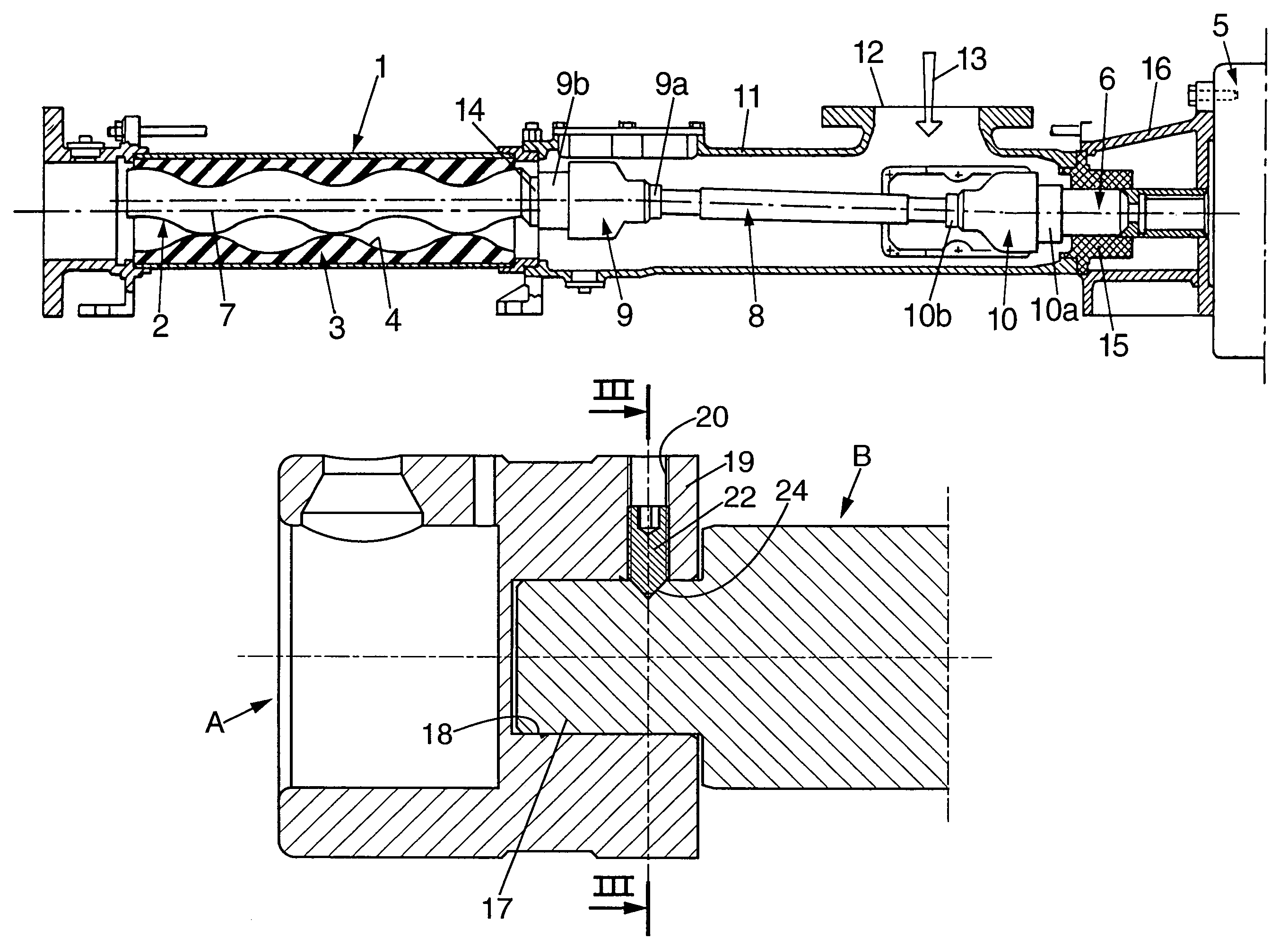
[0029]There now follows a description of the main provisions according to the invention with reference firstly and more particularly to FIG. 2. Although the provisions according to the invention can be implemented to secure any pair of devices A and B connected axially and rotation-wise in the rotary moving gear of the pump shown in FIG. 1 as will become more apparent later, it can be assumed, as an example and to give more definition to the ideas, that FIG. 2 shows (in reverse position relative to the representation of FIG. 1) the half-coupling 10b (device A) of the first articulated coupling 10 and the end of the intermediate shaft 8 (device B).

[0030]According to the invention, the two connected devices A, B are constructed in the form of a male device B including an axial stub 17 and a female device A including an axial housing 18 designed to receive said stub 17 without appreciable play. As can also be seen in FIGS. 3A and 3B, the lateral wall 19 defining said axial housing 18 o...


PUM


Abstract

Pumping system comprising: a progressive cavity pump comprising a helical rotor inside a helical cavity of an outer stator; motor for driving the rotor, with a motor shaft coaxial to the axis of the stator cavity; and an intermediate shaft coupled, at its ends, by respective couplings, to the rotor shaft and to the motor shaft. Two devices consisting of two of these connected parts are constructed as a male device terminated by an axial stub and a female device terminated by an axial housing receiving the stub, at least two radial screws, not aligned, one of which is a cone-point set screw, connected the stub to the female device.

Description

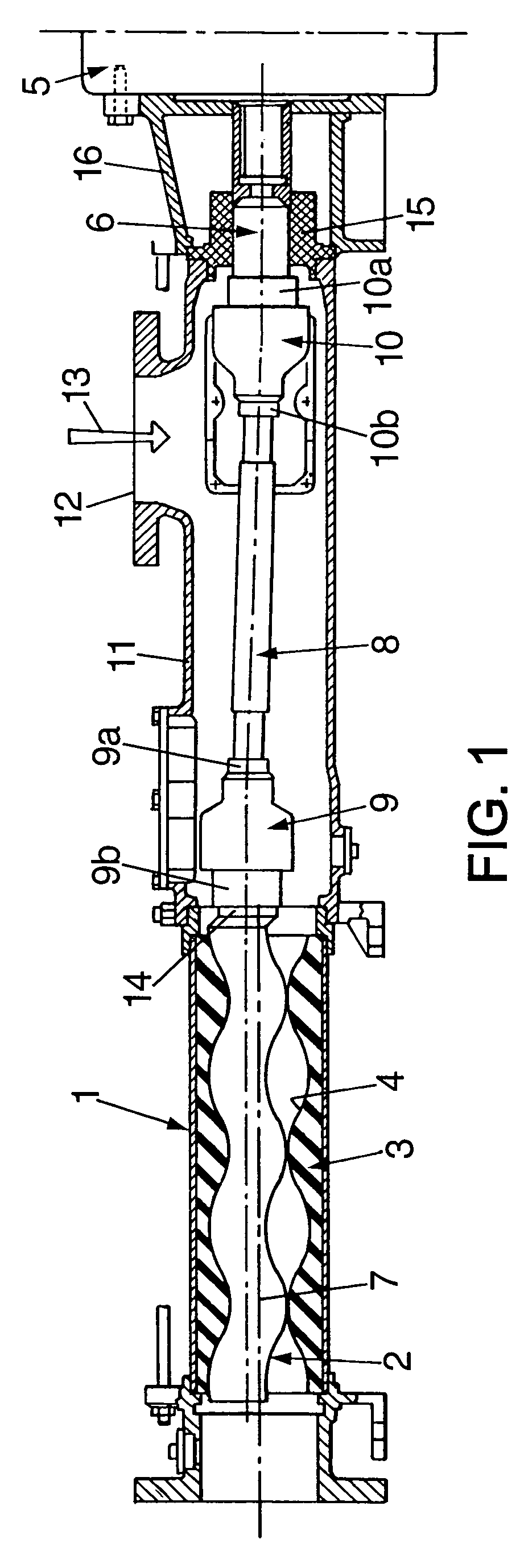
FIELD OF THE INVENTION[0001]The present invention relates to the field of progressive cavity pumps or Moineau pumps.DESCRIPTION OF THE PRIOR ART[0002]The invention relates more particularly to improvements made to a conventional construction of such a pumping system which is illustrated in FIG. 1 of the appended drawings, this pumping system comprising:[0003]a progressive cavity pump 1 comprising a helical rotor 2 inside a helical cavity 4 of an outer stator 3,[0004]motor means 5 for driving the rotor 2, said motor means driving a motor shaft 6 substantially coaxial to the axis of the stator cavity 4,[0005]an intermediate shaft 8 which is coupled rotation-wise both to the motor shaft 6 and to the shaft 14 of the rotor 2,[0006]a first articulated coupling 10 having one end connected to the motor shaft 6 and its other end connected to the intermediate shaft 8,[0007]a second articulated coupling 9 having one end connected to the intermediate shaft 8 and its other end connected to the s...

Claims


Application Information

Patent Timeline
Patent Type & Authority Patents(United States)
IPC IPC(8): F01C1/10F03C2/00F04C18/00
CPCF01C17/06F16D1/0847Y10T403/7041
Inventor MARIELLE, JEAN-PIERRE
Owner PCM TECH
Learn More