Electrical connector

a technology of electrical connectors and connectors, applied in the direction of electrical apparatus, coupling device connections, printed circuits, etc., can solve the problems of affecting the high frequency performance of signal transmission, attenuation, interference, etc., and achieve the effect of improving the high frequency performan

Inactive Publication Date: 2009-01-06
HON HAI PRECISION IND CO LTD
View PDF14 Cites 40 Cited by
  • Summary
  • Abstract
  • Description
  • Claims
  • Application Information

AI Technical Summary

Benefits of technology

[0006]Accordingly, an object of the present invention is to provide an electrical connector with improved high frequency performance.

Problems solved by technology

But crosstalk, impedance, attenuation, propagation delay are the problems affecting high frequency performance of the signal transmission for a long time.
The soldering portions of the contacts are easily to be distorted.
Accordingly, it is hard that the contacts assembled into the holes along an up to down direction, and the high frequency performance of the contacts would have a bad effect.
Furthermore, the insulative housing, the connectors and the spacer are separated from each other which result in a complex structure.

Method used


Image

  • Electrical connector
  • Electrical connector
  • Electrical connector

Examples


Embodiment Construction

[0019]In the following description, numerous specific details are set forth to provide a thorough understanding of the present invention. However, it will be obvious to those skilled in the art that the present invention may be practiced without such specific details. In other instances, well known circuits have been shown in block diagram form in order not to obscure the present invention in unnecessary detail. For the most part, details concerning timing considerations and the like have been omitted inasmuch as such details are not necessary to obtain a complete understanding of the present invention and are within the skills of persons of ordinary skill in the relevant art.

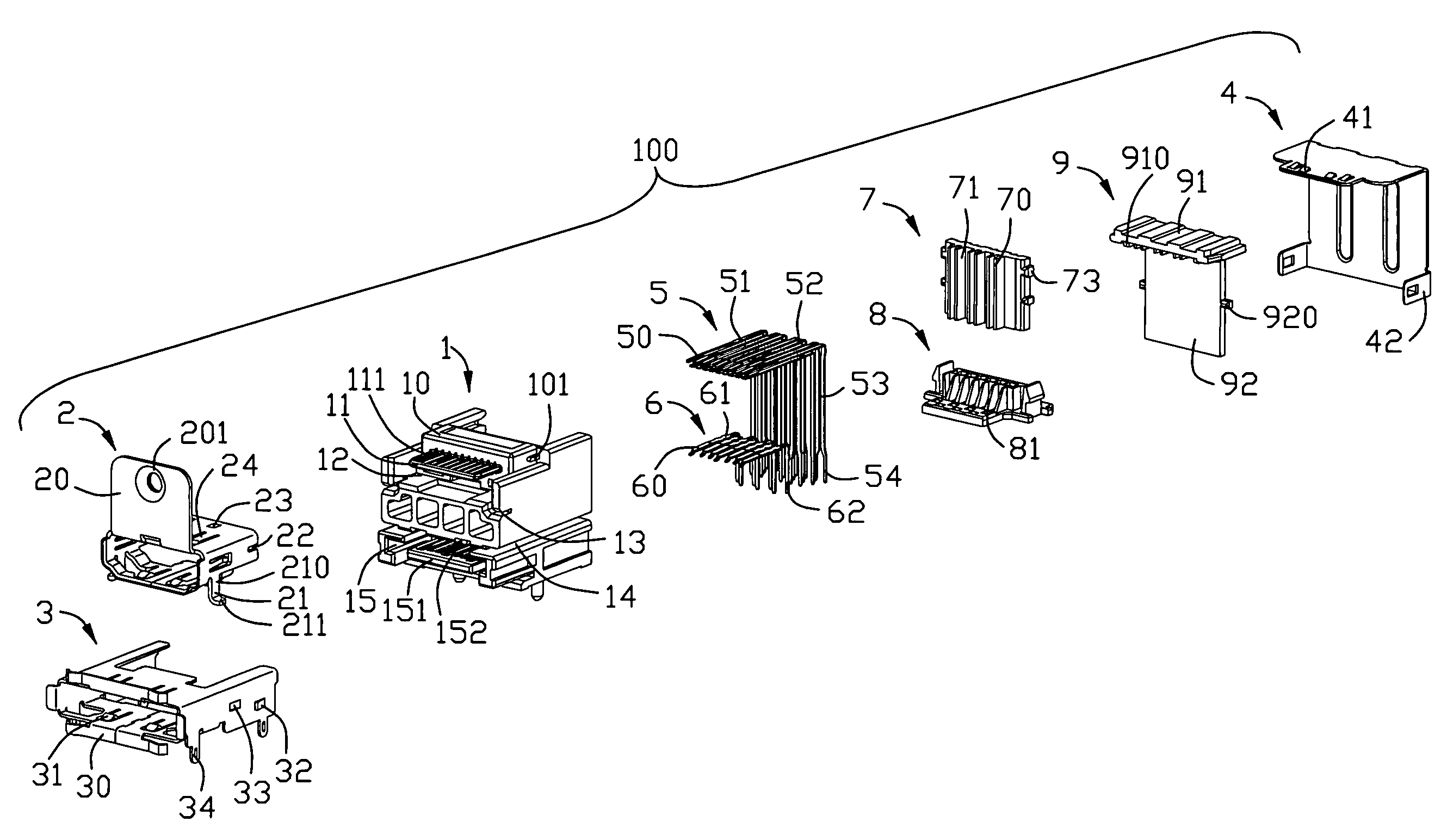
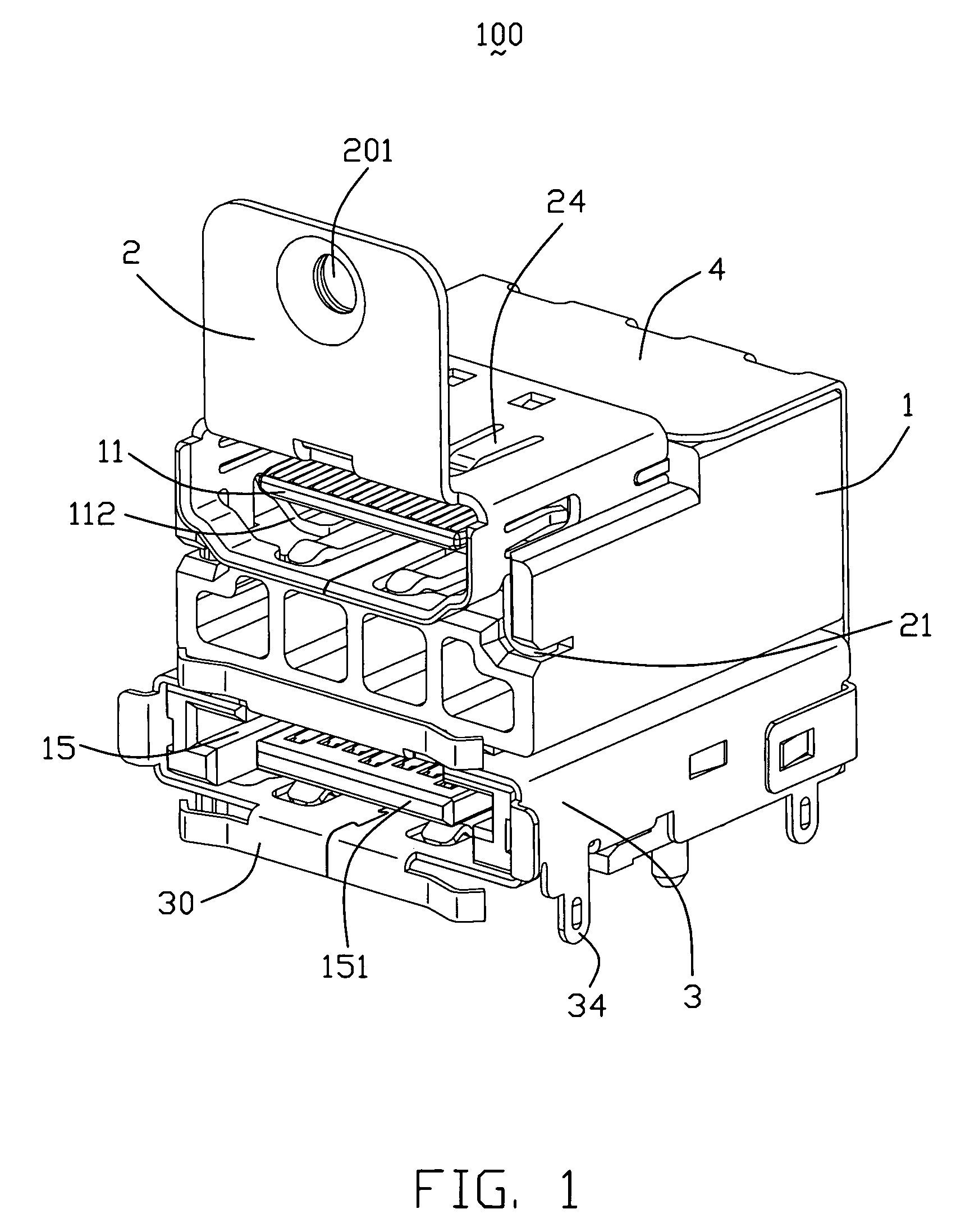
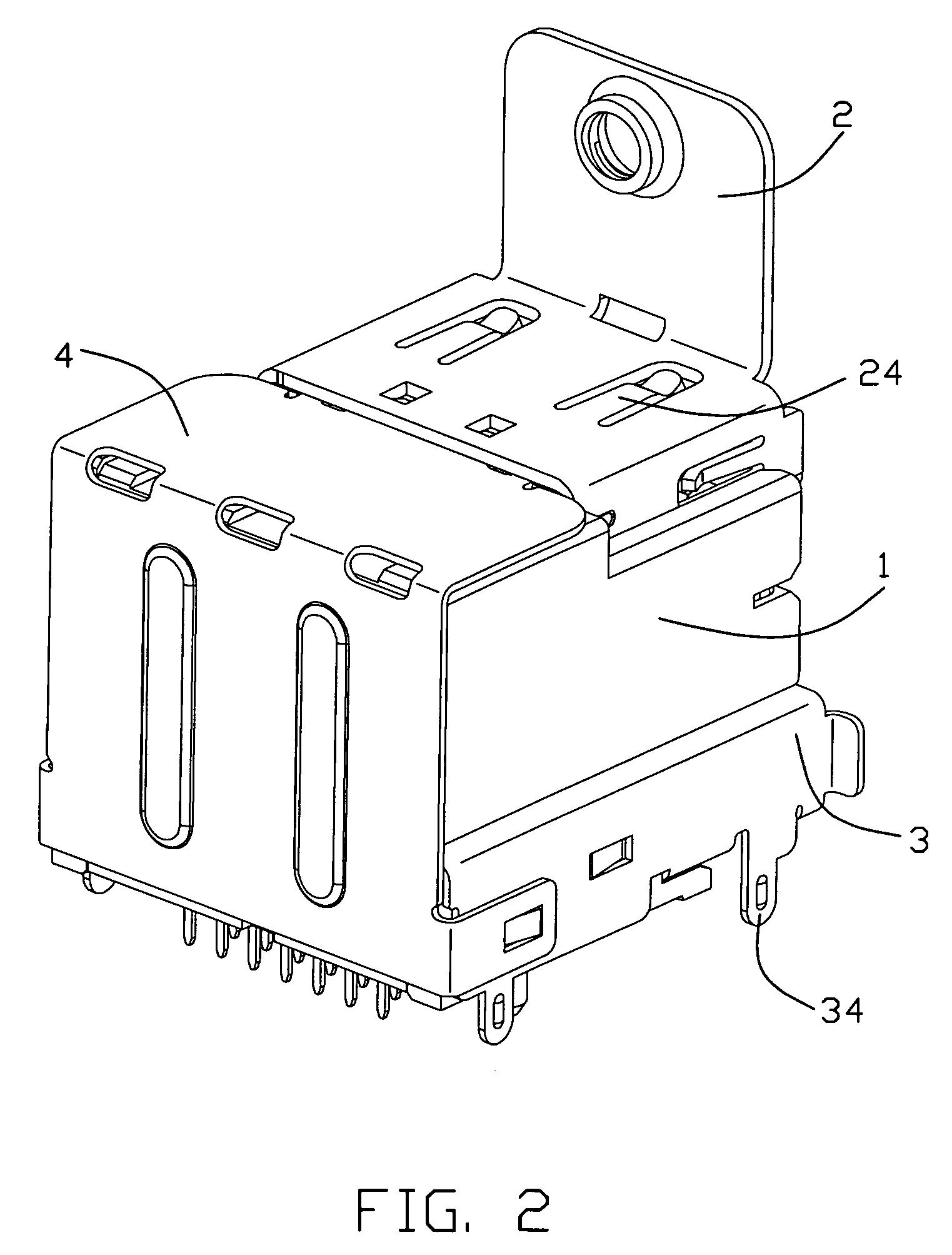
[0020]Referring to FIGS. 19, an electrical connector 100 for mating with a plug (not shown) is disclosed in accordance with the present invention. The electrical connector 100 comprises an insulative housing 1, a shield means mounted on the insulative housing 1, a plurality of contacts retained in the insulativ...


PUM


Abstract

An electrical connector for mating with a plug includes an insulative housing, a number of first contacts retained in the indulative housing. The insulative housing includes a first contact area. Each first contact has a contact portion extending into the first contact area, a soldering portion extending out of the insulative housing and a connecting portion extending therebetween. The connecting portions are arranged in several rows along a front to back direction of the housing. A first spacer is assembled to the insulative housing along the front to back direction and is arranged between the rows of the connecting portions to separate the first contacts from each other.

Description

BACKGROUND OF THE INVENTION[0001]1. Field of the Invention[0002]The present invention relates to electrical connectors, and more particularly to electrical connector with two shielded mating interfaces so as to provide improved performance for high speed signal transmission.[0003]2. Description of Related Art[0004]With high development of electrical industry, the demand of signal transmission is increasing at the same time. But crosstalk, impedance, attenuation, propagation delay are the problems affecting high frequency performance of the signal transmission for a long time. U.S. Pat. No. 6,547,590 B2 discloses a stacked electrical connector which includes an insulative housing with a first connector mounted on an upper position and a second connector mounted on a lower position. Each connector includes a plurality of contacts retained therein. Each contact has a contact portion connecting with a mating plug, a soldering portion connecting with a circuit board and a connecting port...

Claims


Application Information

Patent Timeline
Patent Type & Authority Patents(United States)
IPC IPC(8): H01R13/648
CPCH01R12/716
Inventor HU, PENGHE, JIA-YONGZHENG, QI-SHENG
Owner HON HAI PRECISION IND CO LTD
Why Eureka
Try Eureka