Magnetic resonance imaging coated assembly

a technology of magnetic resonance imaging and assembly, which is applied in the direction of magnetic bodies, cables, therapy, etc., can solve the problems of presenting its own problems, not being suitable for use, and potentially deadly hazards to the organism

Inactive Publication Date: 2009-01-06
BIOPHAN TECH
View PDF179 Cites 50 Cited by
  • Summary
  • Abstract
  • Description
  • Claims
  • Application Information

AI Technical Summary

Problems solved by technology

The insertion of metallic wires into a biological organism (such as, e.g., catheters and guidewires) while the organism is in a magnetic resonance imaging environment poses potentially deadly hazards to the organism through excessive heating of the wires.
. . ” presents its own problems.
The implementation of glass guidewires, optical fibers, etc., solutions would require substantial retooling of the, for example, catheter manufacturing industry and is not a suitable solution for other medical instruments that a physician may wish to employ, e.g. guidewires, stents, etc, during a medical procedure within an MRI system.
None of the prior art compositions or coatings appear to be adapted to both facilitate MRI imaging while simultaneously protecting biological tissue within a living organism from the adverse effects of the MRI electromagnetic wave.

Method used


Image

  • Magnetic resonance imaging coated assembly
  • Magnetic resonance imaging coated assembly
  • Magnetic resonance imaging coated assembly

Examples


Embodiment Construction

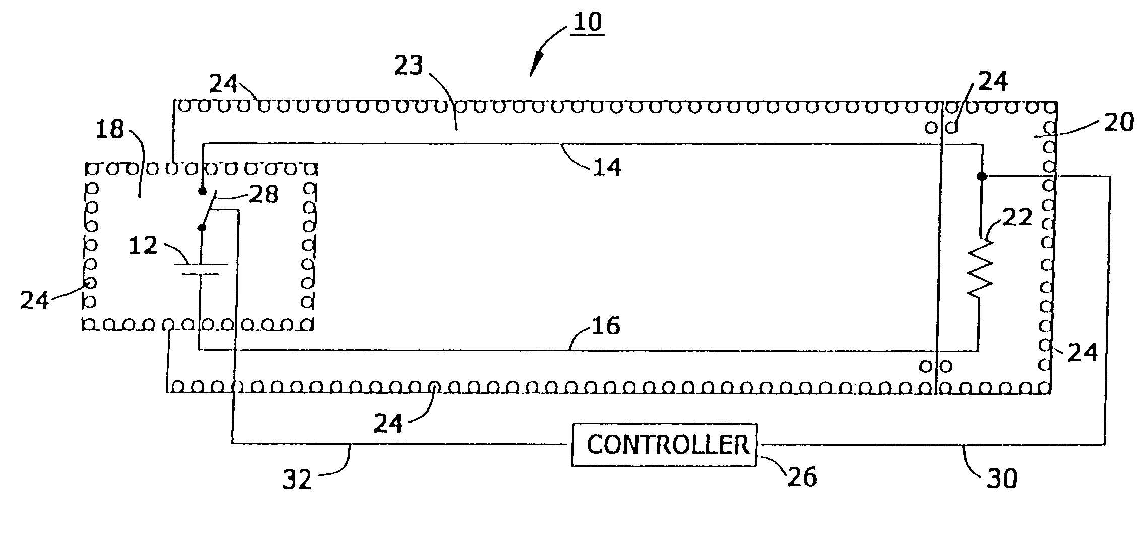
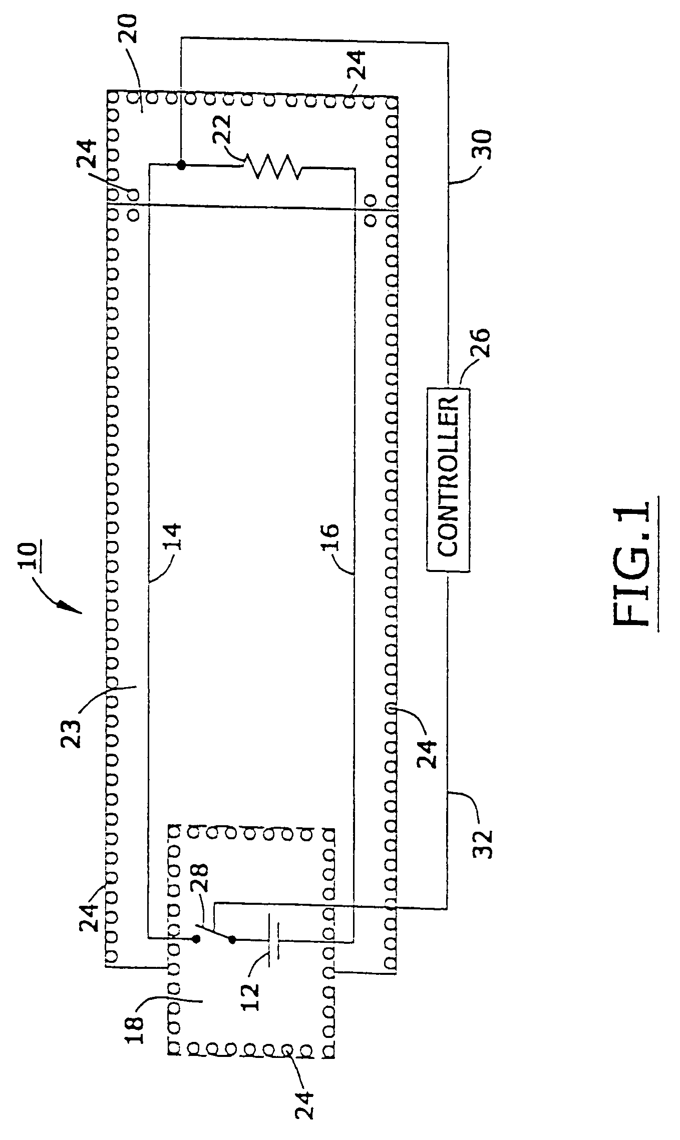
[0062]FIG. 1 is a schematic sectional view of one preferred device 10 that is implanted in a living biological organism (not shown). Device 10 is comprised of a power source 12, a first conductor 14, a second conductor 16, a first insulative shield 18 disposed about power source 12, a second insulative shield 20 disposed about a load 22, a third insulative shield 23 disposed about a first conductor 14, and a second conductor 16, and a multiplicity of nanomagentic particles 24 disposed on said first insulative shield 18 said second insulative shield 20, and said third insulative shield 23.

[0063]In one embodiment, the device 10 is a an implantable device used to monitor and maintain at least one physiologic function that is capable of operating in the presence of damaging electromagnetic interference; see, e.g., United States published patent application U.S. 2002 / 0038135, the entire disclosure of which is hereby incorporated by reference into this specification.

[0064]In one aspect of...


PUM

PropertyMeasurementUnit
particle sizeaaaaaaaaaa
thicknessaaaaaaaaaa
frequencyaaaaaaaaaa

Abstract

An assembly for shielding an implanted medical device from the effects of high-frequency radiation and for emitting magnetic resonance signals during magnetic resonance imaging. The assembly includes an implanted medical device and a magnetic shield comprised of nanomagnetic material disposed between the medical device and the high-frequency radiation. In one embodiment, the magnetic resonance signals are detected by a receiver, which is thus able to locate the implanted medical device within a biological organism.

Description

CROSS-REFERENCE TO RELATED PATENT APPLICATIONS[0001]This application is a continuation of patent application Ser. No. 10 / 838,116 (filed May 3, 2004) which is a continuation-in-part of Ser. No. 10 / 384,288 (filed Mar. 7, 2003, now U.S. Pat. No. 6,765,144), which is a continuation of co-pending application Ser. No. 10 / 324,773 (filed Dec. 18, 2002), Ser. No. 10 / 313,847 (filed Dec. 7, 2002), Ser. No. 10 / 303,264 (filed Nov. 25, 2002, now U.S. Pat. No. 6,713,671), Ser. No. 10 / 273,738 (filed Oct. 18, 2002), Ser. No. 10 / 260,247 (filed Sep. 30, 2002, now U.S. Pat. No. 6,673,999), Ser. No. 10 / 242,969 (filed Sep. 13, 2002), Ser. No. 10 / 229,183 (filed Aug. 26, 2002), Ser. No. 10 / 090,553 (filed Mar. 4, 2002), and Ser. No. 10 / 054,407 (filed Jan. 22, 2002, now U.S. Pat. No. 6,506,972), all incorporated by reference as if fully written out below.FIELD OF THE INVENTION[0002]An assembly for imaging an implanted medical device, wherein the medical device is shielded by nanomagnetic material which, in a...

Claims


Application Information

Patent Timeline
Patent Type & Authority Patents(United States)
IPC IPC(8): H01B11/06A61B5/05A61N1/16G01R33/28G01V3/00H01B7/04H01B11/10H01F10/00H01F10/32
CPCA61K49/1818A61N1/16B82Y5/00B82Y25/00G01R33/286H01B11/10H01B11/1083H01F10/007H01F10/324
Inventor WANG, XINGWUGREENWALD, HOWARD J.HELFER, JEFFREY L.GRAY, ROBERT W.WEINER, MICHAEL L.
Owner BIOPHAN TECH
Why Eureka
Try Eureka